Contents
Please note that these images are for your own use for study and instruction. If you are using these images in a presentation, the reference to the book should always be displayed along with the image. See website for full copyright information.
This edition first published 2009, © 2009 R.X. Stroobandt, S.S. Barold and A.F. Sinnaeve
Blackwell Publishing was acquired by John Wiley & Sons in February 2007. Blackwell’s publishing program has been merged with Wiley’s global Scientific, Technical and Medical business to form Wiley-Blackwell.
Registered office: John Wiley & Sons Ltd, The Atrium, Southern Gate, Chichester, West Sussex, PO19 8SQ, UK
Editorial offices: 9600 Garsington Road, Oxford, OX4 2DQ, UK
The Atrium, Southern Gate, Chichester, West Sussex, PO19 8SQ, UK
111 River Street, Hoboken, NJ 07030-5774, USA
For details of our global editorial offices, for customer services and for information about how to apply for permission to reuse the copyright material in this book please see our website at
The right of the author to be identified as the author of this work has been asserted in accordance with the Copyright, Designs and Patents Act 1988.
All rights reserved. No part of this publication may be reproduced, stored in a retrieval system, or transmitted, in any form or by any means, electronic, mechanical, photocopying, recording or otherwise, except as permitted by the UK Copyright, Designs and Patents Act 1988, without the prior permission of the publisher.
Wiley also publishes its books in a variety of electronic formats. Some content that appears in print may not be available in electronic books.
Designations used by companies to distinguish their products are often claimed as trademarks. All brand names and product names used in this book are trade names, service marks, trademarks or registered trademarks of their respective owners. The publisher is not associated with any product or vendor mentioned in this book. This publication is designed to provide accurate and authoritative information in regard to the subject matter covered. It is sold on the understanding that the publisher is not engaged in rendering professional services. If professional advice or other expert assistance is required, the services of a competent professional should be sought.
The contents of this work are intended to further general scientific research, understanding, and discussion only and are not intended and should not be relied upon as recommending or promoting a specific method, diagnosis, or treatment by physicians for any particular patient. The publisher and the author make no representations or warranties with respect to the accuracy or completeness of the contents of this work and specifically disclaim all warranties, including without limitation any implied warranties of fitness for a particular purpose. In view of ongoing research, equipment modifications, changes in governmental regulations, and the constant flow of information relating to the use of medicines, equipment, and devices, the reader is urged to review and evaluate the information provided in the package insert or instructions for each medicine, equipment, or device for, among other things, any changes in the instructions or indication of usage and for added warnings and precautions. Readers should consult with a specialist where appropriate. The fact that an organization or Website is referred to in this work as a citation and/or a potential source of further information does not mean that the author or the publisher endorses the information the organization or Website may provide or recommendations it may make. Further, readers should be aware that Internet Websites listed in this work may have changed or disappeared between when this work was written and when it is read. No warranty may be created or extended by any promotional statements for this work. Neither the publisher nor the author shall be liable for any damages arising herefrom.
Library of Congress Cataloging-in-Publication Data
Stroobandt, R. (Roland)
Implantable cardioverter-defibrillators step by step : an illustrated guide / Roland X. Stroobandt, S. Serge Barold, Alfons F. Sinnaeve.
p. ; cm.
Sequel to: Cardiac pacemakers step by step / S. Serge Barold, Roland X. Stroobandt, Alfons F. Sinnaeve. c2004.
ISBN 978-1-4051-8638-4
1. Implantable cardioverter-defibrillators—Handbooks, manuals, etc. I. Barold, S. Serge. II. Sinnaeve, Alfons F. III. Barold, S. Serge. Cardiac pacemakers step by step. IV. Title.
[DNLM: 1. Defibrillators, Implantable—Handbooks. 2. Tachycardia, Ventricular—therapy—Handbooks. 3. Death, Sudden, Cardiac—prevention & control—Handbooks. 4. Ventricular Fibrillation—therapy—Handbooks. WG 39 S924i 2009]
RC684.E4S74 2009
617.4’120645—dc22
2008033369
ISBN: 9781405186384
A catalogue record for this book is available from the British Library.
Preface
Implantable Cardioverter-Defibrillators Step By Step is the logical sequel to our first book, Cardiac Pacemakers Step by Step, published in 2004. The pacemaker book should obviously be studied before starting this book because pacing constitutes an integral part of the function of an implantable cardioverter-defibrillator (ICD). The original pacemaker book was so well received that we decided to keep the same format. In addition, 65 carefully selected ICD recordings have been included.
As one picture is worth a thousand words, we have tried to avoid unnecessary text and focused on visual learning. Many of the figures are selfexplanatory and the text in the appendix provides a summary of the field. The relevant figures are cited in the appended text. This arrangement promotes learning as an enjoyable and fun experience.
We have discussed the electrophysiologic aspects of ICD implantation but omitted a description of the standard surgical implantation procedures, which are well described elsewhere. Furthermore, the major ICD trials are mentioned only briefly to avoid reduplication of the abundant literature on the subject. Barring these two issues, which might have rendered the work unwieldy, the book provides a comprehensive review of the basic and clinical aspects of ICD therapy. A section on cardiac resynchronization was added because most patients with such devices also receive an ICD. The rapid evolution of technology made our task a moving target, with the continual need to upgrade some of the material. Despite our efforts, it is possible that some dated material might have escaped our attention, and we apologize for this.
We have discussed only the devices from the three US manufacturers as models, merely for the sake of convenience. We are well aware that manufacturers outside of the United States produce excellent devices. Although a full description of non-US ICDs is beyond the scope of the book, such ICDs share many characteristics with US devices so that the book will be universally applicable to the clinical evaluation of all devices regardless of their origin. We are particularly indebted to representatives of Medtronic Inc., St. Jude Medical and Boston Scientific for helping and guiding us with this project. However, we remain responsible for any mistakes related to ICD technology.
Roland X. Stroobandt
S. Serge Barold
Alfons F. Sinnaeve
Acknowledgments
Carsten Israel MD (Frankfurt, Germany), Michael O. Sweeney MD (Boston, MA), Bengt Herweg MD (Tampa, FL), and representatives from Medtronic Inc., Boston Scientific and St. Jude Medical kindly provided a number of tracings.
Figure 13.381 was reproduced with permission from Mehdirad A, Fredman C, Bierman K, Barold SS. AV interval-dependent crosstalk. Pacing Clin Electrophysiol 2008;31:232–4.
was reproduced with permission from Stroobandt R, Hagers Y, Provenier F, Van Belle Y, Hamerlijnck R, Barold SS. Silent lead malfunction detected only during defibrillator replacement. Pacing Clin Electrophysiol 2006;29:67–9.
was reproduced with permission from Sung RJ, Lauer MR (eds) Implantable cardioverter-defibrillator therapy. In: Fundamental Approaches to the Management of Cardiac Arrhythmias. Dordrecht, The Netherlands: Kluwer Academic Publishers, 2000:287–416.
Parts of the following guideline were reproduced by permission of the American Heart Association.
Zipes DP, Camm AJ, Borggrefe M, Buxton AE, Chaitman B, Fromer M, Gregoratos G, Klein G, Moss AJ, Myerburg RJ, Priori SG, Quinones MA, Roden DM, Silka MJ, Tracy C, Smith SC Jr, Jacobs AK, Adams CD, Antman EM, Anderson JL, Hunt SA, Halperin JL, Nishimura R, Ornato JP, Page RL, Riegel B, Priori SG, Blanc JJ, Budaj A, Camm AJ, Dean V, Deckers JW, Despres C, Dickstein K, Lekakis J, McGregor K, Metra M, Morais J, Osterspey A, Tamargo JL, Zamorano JL. ACC/AHA/ESC 2006 Guidelines for Management of Patients With Ventricular Arrhythmias and the Prevention of Sudden Death—Executive Summary: A Report of the American College of Cardiology/American Heart Association Task Force and the European Society of Cardiology Committee for Practice Guidelines (Writing Committee to Develop Guidelines for Management of Patients With Ventricular Arrhythmias and the Prevention of Sudden Cardiac Death). Developed in collaboration With the European Heart Rhythm Association and the Heart Rhythm Society. J Am Coll Cardiol. 2006;48:e247-346.
Epstein AE, DiMarco JP, Ellenbogen KA, Estes NA 3rd, Freedman RA, Gettes LS, Gillinov AM, Gregoratos G, Hammill SC, Hayes DL, Hlatky MA, Newby LK, Page RL, Schoenfeld MH, Silka MJ, Stevenson LW, Sweeney MO, Smith SC Jr, Jacobs AK, Adams CD, Anderson JL, Buller CE, Creager MA, Ettinger SM, Faxon DP, Halperin JL, Hiratzka LF, Hunt SA, Krumholz HM, Kushner FG, Lytle BW, Nishimura RA, Ornato JP, Page RL, Riegel B, Tarkington LG, Yancy CW; American College of Cardiology/American Heart Association Task Force on Practice Guidelines (Writing Committee to Revise the ACC/AHA/NASPE 2002 Guideline Update for Implantation of Cardiac Pacemakers and Antiarrhythmia Devices); American Association for Thoracic Surgery; Society of Thoracic Surgeons. ACC/AHA/HRS 2008 Guidelines for Device- Based Therapy of Cardiac Rhythm Abnormalities: a report of the American College of Cardiology/ American Heart Association Task Force on Practice Guidelines (Writing Committee to Revise the ACC/AHA/NASPE 2002 Guideline Update for Implantation of Cardiac Pacemakers and Antiarrhythmia Devices) developed in collaboration with the American Association for Thoracic Surgery and Society of Thoracic Surgeons. J Am Coll Cardiol. 2008;51:e1-62.
The authors would also like to thank the nurses and technicians: Veerle De Meyer, Myriam Peleman, Rudy Colpaert, Guy De Cocker of the University Hospital, Ghent, Belgium, and Filiep Vandenbulcke of the A.Z. Damiaan Hospital, Ostend, Belgium, for their dedicated care of ICD patients and ability to recognize the teaching value of a number of recordings included in this book.
Introduction
Sudden cardiac death remains a major public health problem and accounts for 450 000 deaths annually in the United States and 400 000 in Europe. Michel Mirowski began developing an implantable defibrillator in the mid-1960s. The first automatic defibrillator was finally implanted in a human patient in 1980. The device presently known as an implantable cardioverter-defibrillator (ICD) has proven effective in preventing sudden cardiac death. Since 1980, technologic advances in device therapy including miniaturization, improved leads, optimal waveforms and transvenous implantation have revolutionized the treatment of malignant ventricular tachyarrhythmias and sudden cardiac death. These advances have made ICDs easier and safer to implant and better accepted by patients and physicians. Thus, ICDs have evolved from a treatment of last resort to the gold standard for patients at high risk for life-threatening ventricular arrhythmias. Recent advances include dual-chamber ICDs, additional therapy for atrial arrhythmias, and ICDs combined with biventricular pacing for selected heart failure patients. Device-based monitoring of contemporary ICDs can also record data unrelated to arrhythmias such as activity and the status of lung fluid in patients with congestive heart failure. Finally, ICDs provide health benefits with efficiency comparable to other well-accepted forms of health care such as renal dialysis.
The ICD does not prevent arrhythmias from occurring, and it is sometimes likened to having a miniature ambulance crew inside the chest. Shock delivery is the final step in a cascade of events beginning with arrhythmia detection. The device can detect ventricular tachyarrhythmias, determine whether they should be converted to a normal rhythm with a shock or rapid ventricular pacing, and then administer therapy. After successful treatment, the device must recognize the nontachycardic rhythm and reset the therapy sequences for the next event. Afterwards, the device keeps a complete record of what it has done. An ICD also gives bradycardia and post-shock bradycardia support like a conventional pacemaker.
Cardioversion and defibrillation are both forms of high-energy therapy or shocks. If the patient is conscious at the time of a shock, it is painful and usually described as feeling like a kick in the chest. Patients should be advised of this in advance. Their families should be advised that someone touching them is not harmed if the ICD discharges.
ICDs are multiprogrammable devices capable of delivering therapy for ventricular tachyarrhythmias in the form of high-energy defibrillation shocks, low-energy (cardioversion) shocks or antitachycardia pacing, and conventional pacing therapy for bradyarrhythmias (). Today’s devices have a longevity of about 5–7 years, depending on shock and pacing frequency.
Figure 0.01
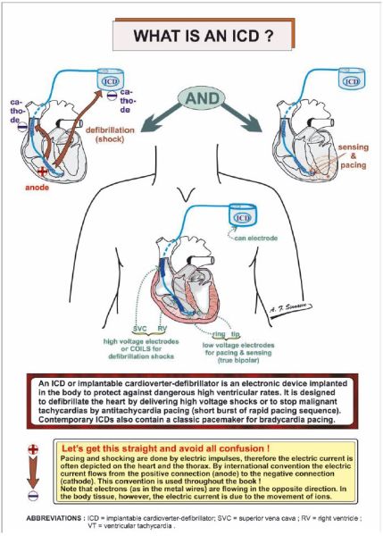
Figure 1.00
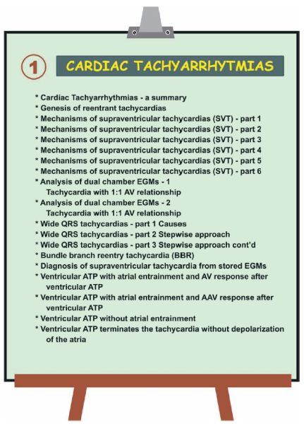
Figure 1.01
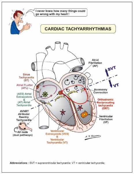
Figure 1.02
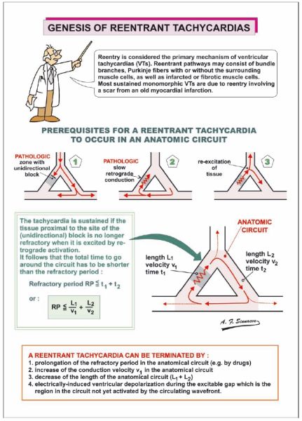
Figure 1.03
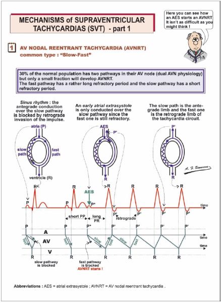
Figure 1.04
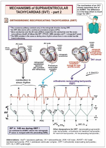
Figure 1.05
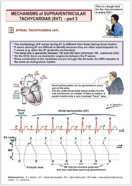
Figure 1.06

Figure 1.07
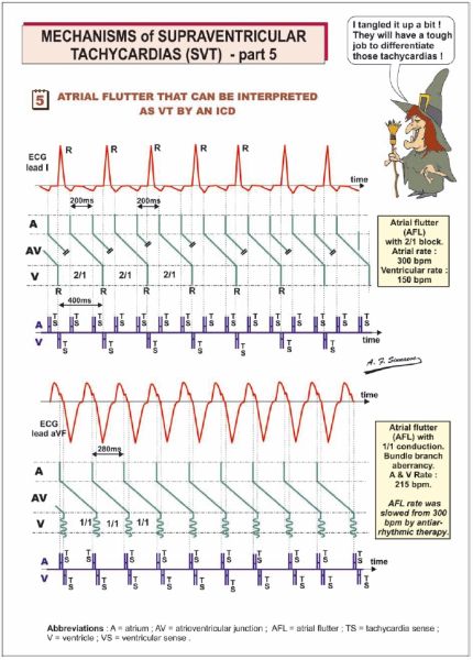
Figure 1.08

Figure 1.09
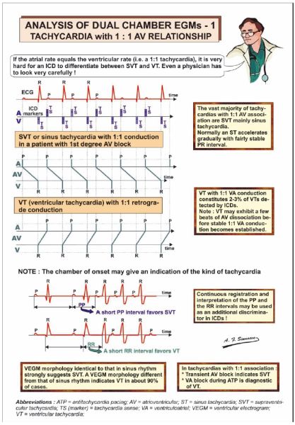
Figure 1.10
Figure 1.11
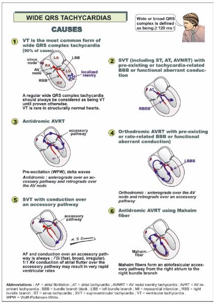
Figure 1.12
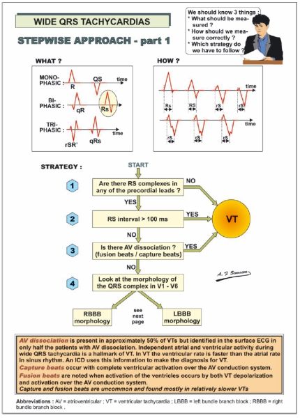
Figure 1.13
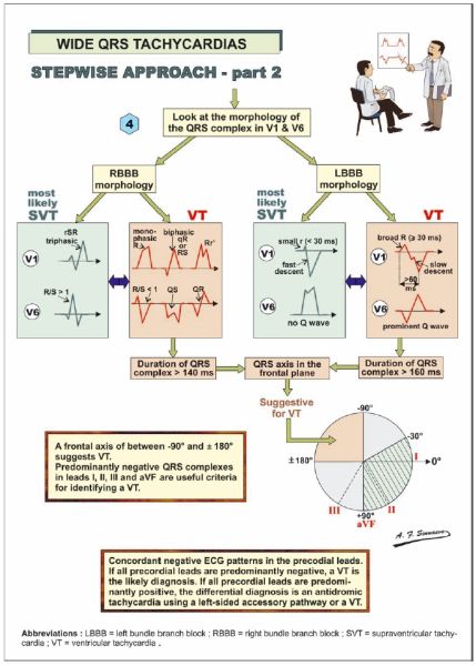
Figure 1.14
Figure 1.15
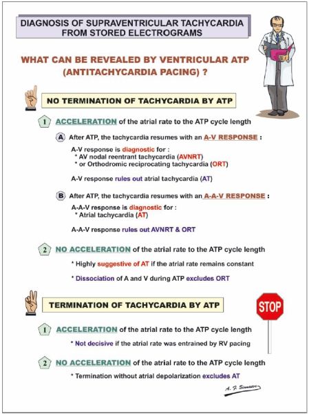
Figure 1.16
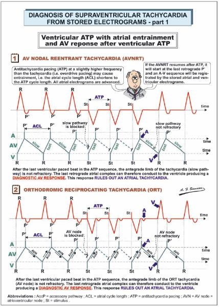
Figure 1.17
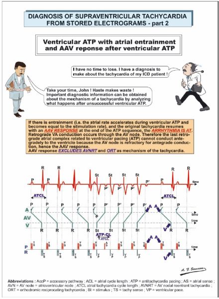
Figure 1.18
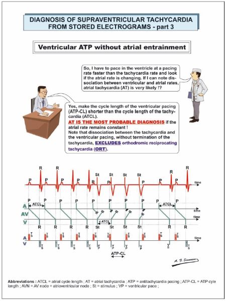
Figure 1.19
Figure 2.00
Figure 2.01
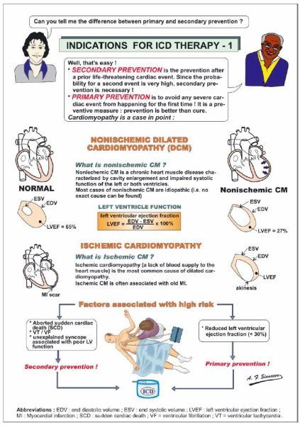
Figure 2.02
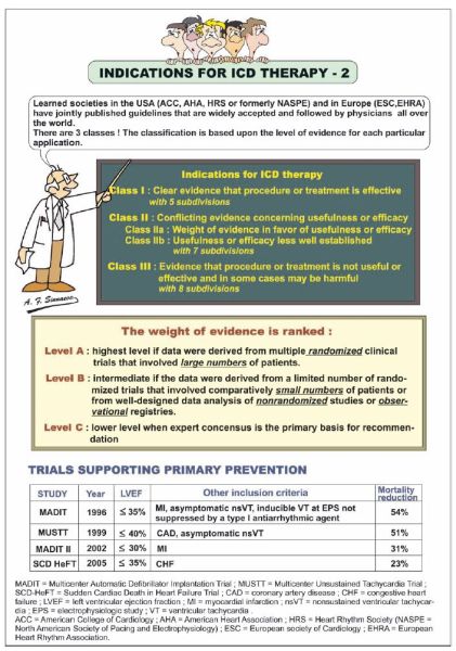
Figure 2.03

Figure 2.04
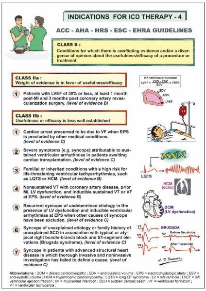
Figure 2.05
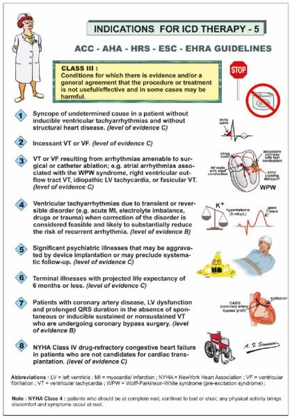
Figure 2.06

Figure 2.07
Figure 2.08

Figure 2.09
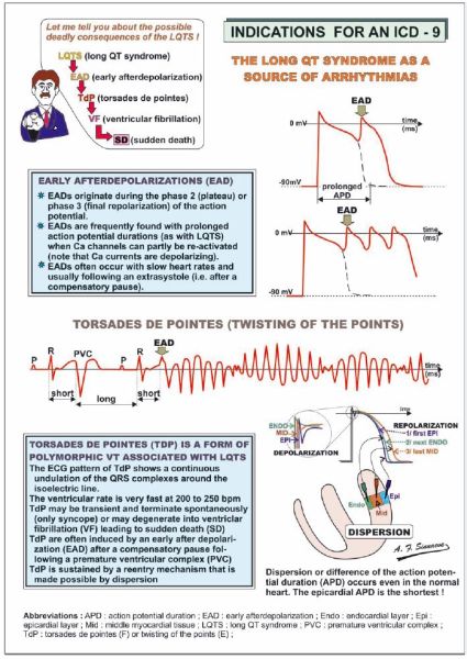
Figure 2.10
Figure 2.11
Figure 2.12
Figure 2.13
Figure 2.14

Figure 2.15
Figure 2.16
Figure 2.17

Figure 3.00
Figure 3.01
Figure 3.02
Figure 3.03

Figure 3.04
Figure 3.05
Figure 3.06

Figure 3.07
Figure 3.08

Figure 3.09
Figure 3.10
Figure 3.11
Figure 3.12
Figure 3.13
Figure 3.14

Figure 3.15
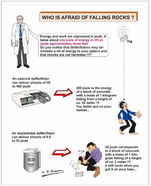
Figure 3.16
Figure 3.17
Figure 3.18
Figure 3.19
Figure 3.20
Figure 3.21
Figure 3.22
Figure 3.23

Figure 3.24

Figure 3.25
Figure 3.26

Figure 3.27
Figure 4.00
Figure 4.01
Figure 4.02
Figure 4.03
Figure 4.04
Figure 4.05
Figure 4.06
Figure 4.07
Figure 4.08
Figure 4.09
Figure 4.10
Figure 4.11
Figure 4.12
Figure 4.13
Figure 4.14
Figure 4.15

Figure 4.16
Figure 4.17
Figure 4.18

Figure 4.19
Figure 4.20
Figure 4.21
Figure 4.22
Figure 5.00
Figure 5.01

Figure 5.02
Figure 5.03
Figure 5.04
Figure 5.05

Figure 5.06
Figure 5.07

Figure 5.08
Figure 5.09
Figure 5.10
Figure 5.11
Figure 5.12
Figure 5.13
Figure 5.14
Figure 5.15
Figure 5.16

Figure 5.17
Figure 5.18

Figure 5.19
Figure 5.20

Figure 5.21

Figure 6.00
Figure 6.01
Figure 6.02

Figure 6.03
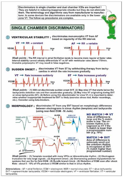
Figure 6.04
Figure 6.05
Figure 6.06
Figure 6.07

Figure 6.08
Figure 6.09

Figure 6.10

Figure 6.11
Figure 6.12
Figure 6.13
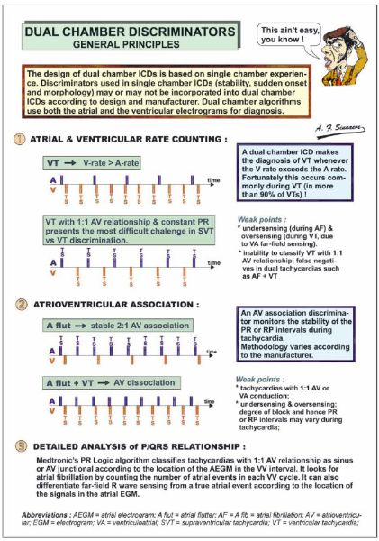
Figure 6.14
Figure 6.15
Figure 6.16

Figure 6.17
Figure 6.18
Figure 6.19
Figure 6.20

Figure 6.21
Figure 6.22

Figure 6.23
Figure 6.24
Figure 6.25
Figure 6.26
Figure 6.27
Figure 6.28

Figure 6.29
Figure 6.30
Figure 6.31
Figure 7.00
Figure 7.01
Figure 7.02
Figure 7.03
Figure 7.04
Figure 7.05
Figure 7.06

Figure 7.07
Figure 7.08

Figure 7.09
Figure 7.10
Figure 7.11
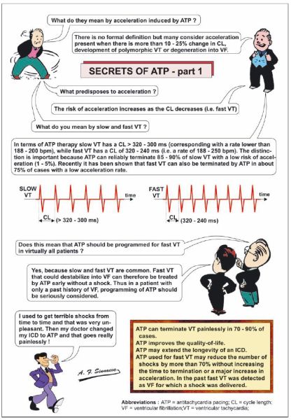
Figure 7.12
Figure 7.13
Figure 7.14

Figure 7.15
Figure 7.16
Figure 7.17
Figure 7.18
Figure 7.19
Figure 7.20
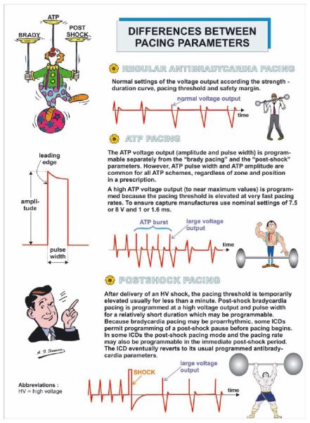
Figure 7.21
Figure 7.22
Figure 7.23

Figure 8.00
Figure 8.01
Figure 8.02

Figure 8.03
Figure 8.04
Figure 8.05

Figure 8.06
Figure 8.07

Figure 9.00
Figure 9.01
Figure 9.02
Figure 9.03
Figure 9.04
Figure 9.05
Figure 9.06
Figure 9.07
Figure 9.08
Figure 9.09
Figure 9.10
Figure 9.11
Figure 9.12
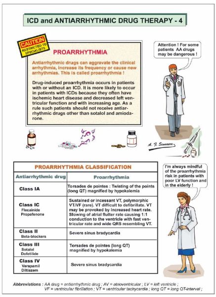
Figure 9.13
Figure 9.14
Figure 9.15
Figure 9.16
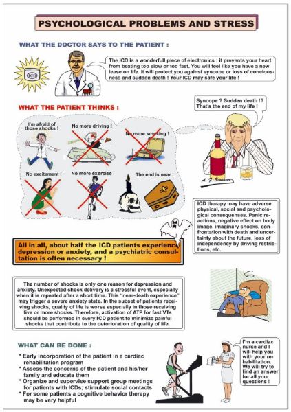
Figure 9.17
Figure 9.18
Figure 10.00
Figure 10.01
Figure 10.02
Figure 10.03
Figure 10.04
Figure 10.05
Figure 10.06

Figure 10.07
Figure 10.08
Figure 10.09
Figure 10.10
Figure 10.11
Figure 10.12
Figure 10.13
Figure 10.14
Figure 10.15
Figure 10.16
Figure 10.17
Figure 10.18
Figure 10.19
Figure 10.20
Figure 10.21
Figure 11.00
Figure 11.01
Figure 11.02
Figure 11.03
Figure 11.04
Figure 11.05
Figure 11.06

Figure 11.07
Figure 11.08
Figure 11.09
Figure 11.10
Figure 11.11

Figure 12.00
Figure 12.01

Figure 12.02
Figure 12.03
Figure 12.04
Figure 12.05
Figure 12.06

Figure 12.07
Figure 12.08
Figure 12.09
Figure 12.10
Figure 12.11

Figure 12.12
Figure 12.13
Figure 12.14
Figure 12.15
Figure 12.16
Figure 12.17
Figure 12.18
Figure 12.19
Figure 12.20
Figure 12.21
Figure 12.22
Figure 12.23
Figure 12.24
Figure 12.25
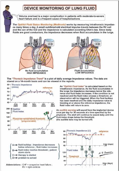
Figure 13.00
Figure 13.01

Figure 13.02
Figure 13.03
Figure 13.04

Figure 13.05

Figure 13.06
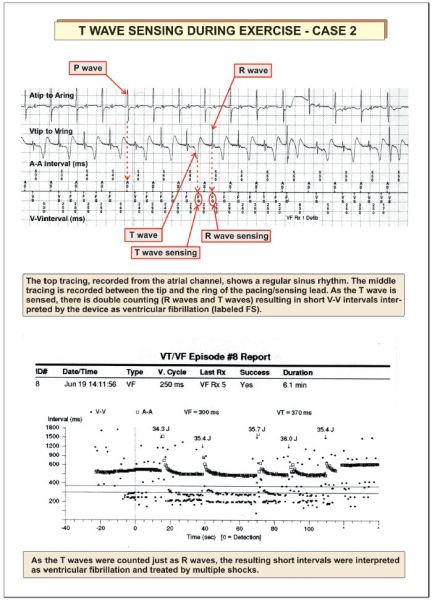
Figure 13.07
Figure 13.08
Figure 13.09

Figure 13.10
Figure 13.11
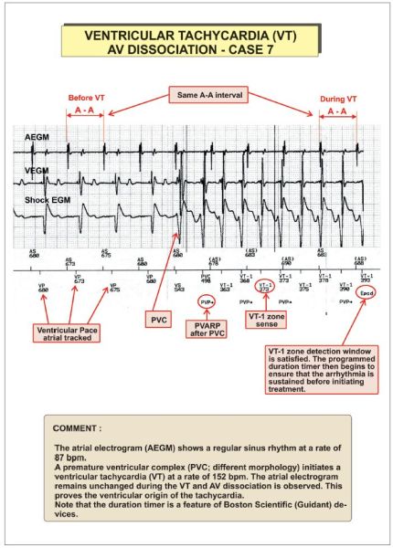
Figure 13.12
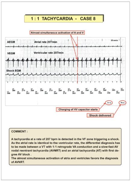
Figure 13.13

Figure 13.14
Figure 13.15
Figure 13.16
Figure 13.17
Figure 13.18
Figure 13.19
Figure 13.20

Figure 13.21
Figure 13.22
Figure 13.23
Figure 13.24

Figure 13.25

Figure 13.26
Figure 13.27

Figure 13.28
Figure 13.29

Figure 13.30
Figure 13.31
Figure 13.32

Figure 13.33
Figure 13.34

Figure 13.35
Figure 13.36
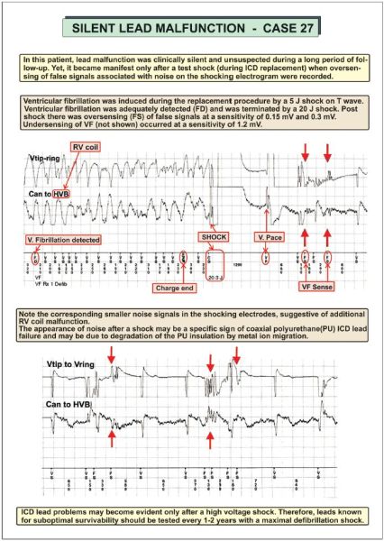
Figure 13.37
Figure 13.38
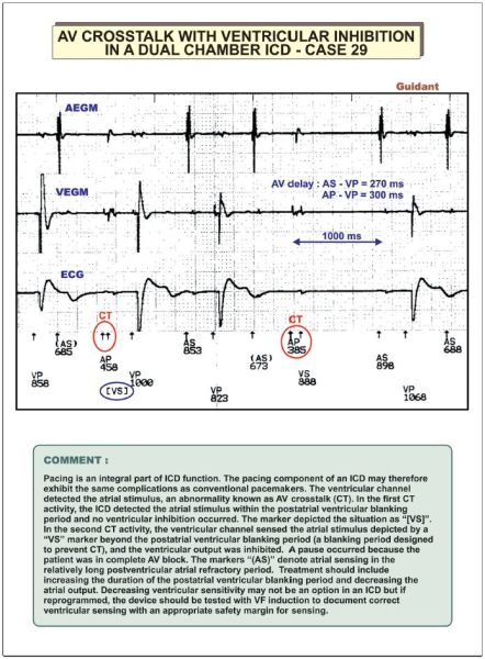
Figure 13.39
Figure 13.40
Figure 13.41
Figure 13.42

Figure 13.43
Figure 13.44
Figure 13.45
Figure 13.46
Figure 13.47
Figure 13.48
Figure 13.49
Figure 13.50
Figure 13.51
Figure 13.52

Figure 13.53
Figure 13.54

Figure 13.55
Figure 13.56
Figure 13.57
Figure 13.58
Figure 13.59

Figure 13.60

Figure 13.61
Figure 13.62
Figure 13.63
Figure 13.64
Figure 13.65
Figure 13.66
Figure 13.67
Figure 13.68
Figure 13.69
Figure 13.70
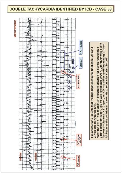
Figure 13.71

Figure 13.72
Figure 13.73
Figure 13.74
Figure 13.75
Figure 13.76

Cardiac tachyarrhythmias are subdivided into supraventricular and ventricular arrhythmias ().
There are three basic mechanisms of arrhythmias common to both atrial and ventricular arrhythmias: automaticity, afterdepolarizations and reentry.
Slow conduction in the loop allows the previously blocked pathway time to recover excitability. A critically timed impulse conducts anterogradely through the only open pathway and returns retrogradely via the other pathway responsible for unidirectional block. If the anterograde pathway has recovered from refractoriness, the returning impulse can then reactivate the earlier site and start a self-perpetuating reentrant tachycardia ().
The maintenance of supraventricular tachyarrhythmias (SVT) involves structures above the division of the His bundle. Supraventricular tachyarrhythmias comprise atrial tachycardia (AT), atrial flutter (AFL), atrial fibrillation (AF) and atrioventricular (AV) junctional tachycardias. Atrioventricular junctional tachycardias include AV nodal reentrant tachycardia (AVNRT) and AV reentrant (orthodromic reciprocating) tachycardia (AVRT/ORT) incorporating one or more accessory AV pathways in a reentry circuit.
Atrioventricular nodal reentrant tachycardia (AVNRT) involves an AV nodal reentry circuit that consists of two atrionodal connections or pathways and a component of atrial myocardium joining them.
The common type of AVNRT (slow–fast) involves two functionally and anatomically separate atrionodal pathways with different refractory periods. The fast conducting pathway possesses a long refractory period and the slow pathway a short refractory period. During sinus rhythm, anterograde conduction proceeds simultaneously over both AV nodal pathways but retrograde invasion of the impulse coming from the fast pathway blocks anterograde conduction over the slow pathway. The tachycardia typically starts with a premature atrial beat with critical timing that finds the fast pathway refractory but open conduction over the nonrefractory slow pathway (with a long PR-interval). Upon reaching the lower common pathway of the reentry circuit, the wavefront returns retrogradely to the atria via the fast pathway. The process establishes a reentrant SVT using the slow pathway as the anterograde limb and the fast pathway as the retrograde limb (). Atrial and ventricular activation occur nearly simultaneously. During the common slowfast AVNRT, retrograde P-waves hide within the QRS complex or emerge at the end of the QRS complex producing terminal “pseudo s waves” in the inferior leads or more frequently “pseudo r waves” in lead V1. Rarely the P-wave precedes the beginning of the QRS complex, resulting in “pseudo-q waves” in the inferior leads.
The reverse form of AVNRT (fast–slow AVNRT) is rare. It engages the fast pathway as the anterograde limb and the slow pathway as the retrograde limb of the reentry circuit.
Orthodromic reciprocating tachycardia (ORT) often occurs in patients with an obvious accessory pathway (atrium to ventricle as in the Wolff–Parkinson–White syndrome). However, some patients show no evidence of preexcitation during sinus rhythm because the accessory pathway can only conduct in the retrograde direction from ventricle to atrium. In this situation, an ORT utilizes the accessory pathway as the retrograde limb and the AV node as the anterograde limb of a reentry circuit (). Orthodromic reciprocating tachycardia usually starts with either an atrial or ventricular premature beat. When the accessory pathway conducts rapidly, the retrograde P-wave is inscribed at approximately 140 ms (range 80–160 ms) after the QRS complex with an RP interval shorter than the PR interval. The QRS complex is identical to that during sinus rhythm unless rate-related bundle branch aberrancy supervenes.
Atrial tachycardia can originate from anywhere in the atria. The mechanisms are unclear but may be related either to localized atrial reentry or a focus of enhanced automaticity. The atrial rate generally runs between 150 and 200 b.p.m. but occasionally as fast as 300 b.p.m. During atrial tachycardia the P-wave precedes the QRS complex. The morphology of the P-wave depends on the site of origin and differs from the sinus P-wave. The ventricular rate depends on AV nodal transmission. The AV relationship can be 1:1, or governed by second-degree AV block, which may itself also be variable (). The QRS complex remains the same as during sinus rhythm.
Atrial flutter (AFL) is sustained by a macro-reentrant atrial tachycardia usually located in the right atrium. During the common “typical” counterclockwise (CCW) right AFL the activation wavefront proceeds in a caudo-cranial direction along the interatrial septum. Then it returns cranio-caudally down the right atrial free wall towards the cavo-tricuspid isthmus (the area between the inferior vena cava and tricuspid valve) where there is marked slowing of conduction. During the less common “reverse typical” type of right AFL the macroreentry circuit rotates in a clockwise (CW) direction, down the interatrial septum and up the right atrial free wall ().
In typical CCW AFL, atrial activity (F-waves) inscribes a characteristic “saw-tooth” configuration with a dominant negative deflection in the inferior leads. In the uncommon CW AFL the inferior leads register positive flutter waves. The atrial rate approximates 300 b.p.m., and the AV ratio is usually 2:1 or greater depending on the status of AV nodal conduction. The AV ratio may change irregularly. Atrial flutter can also occur in the left atrium, especially after pulmonary vein isolation (ablation) for the treatment of atrial fibrillation.
A 1:1 AV ratio is exceptional. It may result from the proarrhythmic effect of class IC antiarrhythmic drugs that reduce atrial conduction velocity. The marked slowing of the atrial rate (190–240 b.p.m.) () permits the development of 1:1 “slow” AFL with rate-related bundle branch block – a situation often misdiagnosed as ventricular tachycardia (VT).
The electrophysiologic basis of atrial fibrillation remains obscure. Two major hypotheses prevail:
During atrial fibrillation the fibrillatory waves (f-waves) exhibit a rate of 350–500/min. Only part of the many atrial impulses actually travel at irregular intervals through the AV nodal filter to the ventricles. The electrocardiogram (ECG) shows an irregular ventricular response. The ventricular rate becomes regular and not fast, only in combination with complete AV block. In the presence of a fast ventricular response (> 170 b.p.m.), the ventricular rate tends to regularize, and an implantable cardioverter defibrillator (ICD) may therefore face difficulty in discriminating atrial fibrillation from ventricular tachycardia.
Ventricular tachycardia (VT) and ventricular fibrillation (VF) are the major causes of sudden cardiac death in patients with structural heart disease. Ventricular fibrillation (VF) and/or ventricular tachycardia (VT) can also occur far less commonly in patients with structurally normal hearts. Sudden cardiac death is defined as death from an unsuspected circulatory arrest, usually due to an arrhythmia occurring within an hour of the onset of symptoms and when medical intervention such as defibrillation reverses the event.
Ventricular tachycardia is defined as three or more consecutive premature ventricular complexes with a QRS duration > 120 ms at a rate between 100 and 300 b.p.m. The QRS complexes are not preceded by atrial deflections. The VT may be monomorphic or polymorphic. Monomorphic VT consists of a stable (organized) single QRS morphology often with a left bundle or right bundle block pattern. Polymorphic or multiformic VT exhibits an irregularly changing QRS configuration with variable cycle lengths between 600 and 180 ms. Torsades de pointes is a form of polymorphic VT associated with a long QT interval and characterized by twisting of the peaks of the QRS complexes.
Ventricular tachycardia may be sustained (duration > 30 s) and/or require termination due to hemodynamic compromise in less than 30 s) or non-sustained (three or more beats but less than < 30 s).
Special types of VT include:
This type of VT runs usually close to 300 b.p.m. At fast rates, VT is so rapid that one cannot distinguish the QRS complexes from the T-wave. In other words there is no isoelectric interval between successive QRS complexes. This tachycardia is regular with cycle length variability of 30 ms or less.
Ventricular fibrillation produces a completely disorganized tachyarrhythmia usually faster than 300/min with chaotic, random, asynchronous electrical activity of the ventricles. There are no discrete QRS complexes. Ventricular fibrillation shows marked variability of QRS cycle length, morphology and amplitude. For ICD work, VF may be defined as a polymorphic rhythm with a cycle length < 250 ms associated with no blood pressure. Spontaneous VF is often preceded by organized monomorphic VT. At its onset, VF registers a coarse electrical pattern. As the heart becomes less viable the fibrillation becomes fine and then as an agonal event all electrical activity ceases (flat line).
There are various causes of tachycardia with a wide QRS complex ():
Despite numerous established criteria for the differentiation of ventricular from supraventricular tachycardia (SVT) with aberrant conduction, the differential diagnosis of a wide QRS complex tachycardia (QRS > 120 ms) remains a challenge.
Stepwise approach ()
Step 1: Absence of RS complexes in any of the precordial leads
The absence of RS complexes in any precordial lead strongly suggests VT. If RS complexes are present proceed to step 2.
Step 2: Duration of RS interval in the precordial leads
An interval of the R-wave onset to the S-nadir > 100 ms favors VT.
Step 3: Atrioventricular dissociation, capture or fusion beats
The presence of AV dissociation, i.e. independent atrial and ventricular activity, during a wide QRS tachycardia is diagnostic of VT. It occurs in about half the VT cases; in the other half there is retrograde VA conduction. With 1:1 retrograde VA conduction, the AV/VA relationship cannot differentiate VT from SVT. The presence of second-degree VA conduction block indicates VT.
During relatively slow VT, part of or all the ventricles may be activated by a supraventricular impulse (e.g. sinus beat) conducted through the AV junction. This phenomenon results in “capture beats” (with supraventricular QRS configuration) reflecting complete ventricular activation from the impulse coming from AV node. “Fusion beats” (intermediate QRS morphology) occur when both the ectopic ventricular impulse and a supraventricular beat activate the ventricle to a varying degree. These phenomena are diagnostic of VT.
Step 4: QRS morphologies in V1 and V6
Ventricular tachycardias may present either with a right (RBBB) or left bundle branch block (LBBB) pattern ().
SVTs with RBBB usually display a triphasic pattern in V1 and V6. Lead V1 shows an rSR’ pattern, lead V6 shows a narrow q wave and the R/S ratio is typically > 1.
VTs with RBBB show a monophasic or biphasic QRS complex in lead V1. The presence of a deep S wave with an R/S ratio < 1 or QS or QR pattern in lead V6 supports the diagnosis of VT.
SVTs with LBBB show a narrow r wave (< 30 ms) in lead V1 with a fast downstroke of the S wave. The interval from the onset of the QRS to the nadir of the S wave measures < 60 ms.
VTs with LBBB show in lead V1 a broad R wave (≥ 30 ms) and a slow descent from the beginning of the QRS to the nadir of the S wave (> 60 ms). A prominent Q wave in lead V6 is diagnostic for VT. QRS duration
VT is the most probable diagnosis when QRS duration is > 140 ms in patients with a RBBB configuration and > 160 ms in LBBB in the absence of antiarrhythmic drug therapy.
QRS axis in the frontal plane
A frontal plane QRS axis between − 90° and ± 180° (right superior axis) suggests VT. Thus, mostly negative QRS complexes in leads I, II and III are useful criteria for identifying VT.
Concordant negative ECG patterns in the precordial leads
If all precordial leads generate predominantly negative QRS deflections, VT is the likely diagnosis. If all precordial leads are mostly positive, the differential diagnosis consists of VT and an antidromic tachycardia using a left-sided accessory pathway anterogradely.
The indications for ICD implantation have expanded over the past few years. In addition to secondary prevention for patients with prior life-threatening events, ICDs are now implanted for primary prevention in patients without a prior event but at high risk for sudden death (see appendix and ).
The American College of Cardiology (ACC) and the American Heart Association (AHA) together with the Heart Rhythm Society (HRS) have issued guidelines on ICD indications (; see Appendix). These guidelines represent the consensus of medical opinion as to the use of ICDs. Guidelines use a class system (class I to III) for indications and rank the weight of evidence in levels (level A to C).
The guidelines describe indications as class I as a condition for which there is evidence and/or general agreement that ICD implantation is useful and effective (). Class II indications are conditions for which there is conflicting evidence concerning usefulness or efficacy; in class IIa () the weight of opinion favors ICD implantation, whereas in class IIb the evidence generally opposes use of an ICD. Class III includes several patient populations for whom the consensus of medical opinion holds that ICD implantation is not useful or effective and in some cases may be harmful ().