

Table of Contents
Related Titles
Title Page
Copyright
Foreword by Professor Graeme Clark
References
Acknowledgments
Chapter 1: Medical Bionics
1.1 Medical Bionic Devices
1.2 Key Elements of a Medical Bionic Device
References
Chapter 2: Carbon
2.1 Introduction to Carbon
2.2 Graphene
2.3 Carbon Nanotubes
2.4 Summary
References
Chapter 3: Organic Conducting Polymers
3.1 Polypyrrole
3.2 Polythiophenes
3.3 Polyanilines
3.4 Properties of OCPs
3.5 Chemical-Biological Properties
3.6 Mechanical Properties
3.7 Surface Morphology
3.8 Conclusions
References
Chapter 4: Organic Conductors – Biological Applications
4.1 Carbon Structures for Medical Bionics
4.2 Carbon Nanotubes
4.3 Graphene
4.4 Conducting Polymers
4.5 Toxicity
4.6 Sterilization
References
Chapter 5: Materials Processing/Device Fabrication
5.1 Introduction
5.2 Conducting Polymers
5.3 Carbon Nanotubes
5.4 Graphene
5.5 Composites with Conventional Polymers–a Medical Focus
5.6 3-D Structured Materials and Device Fabrication
References
Chapter 6: Organic Bionics – Where Are We? Where Do We Go Now?
6.1 Materials Design and Selection
6.2 Materials Synthesis and Processing
6.3 Flexible and Printable Electronics
6.4 Characterization
References
Index
Related Titles
Mano, J. F. (ed.)
Biomimetic Approaches for Biomaterials Development
2012
Hardcover
ISBN: 978-3-527-32916-8
Fratzl, P., Harrington, M. J.
Introduction to Biological Materials Science
2013
Hardcover: ISBN: 978-3-527-32971-7
Softcover: ISBN: 978-3-527-32940-3
Öchsner, A., Ahmed, W. (eds.)
Biomechanics of Hard Tissues
Modeling, Testing, and Materials
2010
Hardcover
ISBN: 978-3-527-32431-6
Carpi, F., Smela, E. (eds.)
Biomedical Applications of Electroactive Polymer Actuators
2009
Hardcover
ISBN: 978-0-470-77305-5
Hadziioannou, G., Malliaras, G. G. (eds.)
Semiconducting Polymers
Chemistry, Physics and Engineering
2007
Hardcover
ISBN: 978-3-527-31271-9

The Authors
Prof. Gordon G. Wallace
AIIM Facility
University of Wollongong
ARC Centre of Excellence for
Electromaterials Science/
Intelligent Polymer
Research Institute
Wollongong
New South Wales 2522
Australia
Dr. Simon E. Moulton
AIIM Facility
University of Wollongong
ARC Centre of Excellence for
Electromaterials Science/
Intelligent Polymer
Research Institute
Wollongong
New South Wales 2522
Australia
Prof. Robert M. I. Kapsa
The University of Wollongong
St Vincent's Hospital
41 Victoria Pde, Fitzroy
Victoria 3065
Australia
Dr. Michael J. Higgins
AIIM Facility
University of Wollongong
ARC Centre of Excellence for
Electromaterials Science/
Intelligent Polymer
Research Institute
Wollongong
New South Wales 2522
Australia
All books published by Wiley-VCH are carefully produced. Nevertheless, authors, editors, and publisher do not warrant the information contained in these books, including this book, to be free of errors. Readers are advised to keep in mind that statements, data, illustrations, procedural details or other items may inadvertently be inaccurate.
Library of Congress Card No.: applied for
British Library Cataloguing-in-Publication Data
A catalogue record for this book is available from the British Library.
Bibliographic information published by the Deutsche Nationalbibliothek
The Deutsche Nationalbibliothek lists this publication in the Deutsche Nationalbibliografie; detailed bibliographic data are available on the Internet at <http://dnb.d-nb.de>.
© 2012 Wiley-VCH Verlag & Co. KGaA, Boschstr. 12, 69469 Weinheim, Germany
All rights reserved (including those of translation into other languages). No part of this book may be reproduced in any form — by photoprinting, microfilm, or any other means — nor transmitted or translated into a machine language without written permission from the publishers. Registered names, trademarks, etc. used in this book, even when not specifically marked as such, are not to be considered unprotected by law.
Print ISBN: 978-3-527-32882-6
ePDF ISBN: 978-3-527-64605-0
ePub ISBN: 978-3-527-64604-3
Mobi ISBN: 978-3-527-64603-6
oBook ISBN: 978-3-527-64602-9
Foreword by Professor Graeme Clark
The advent of the bionic ear relied on the identification, optimization and development of appropriate materials that would provide an effective biological – electronic interface [1]. It also needed the development of appropriate electronics and communications (software) strategies and most critically the effective integration of a range of skills and their accompanying personalities to form a multidisciplinary research and clinical team that could ensure success.
The discovery of organic conductors (by MacDiarmid, Shirakawa and Heeger [2] in 1976) provided a new set of materials with properties that have excited those involved in bionics research. Their stimuli-responsive, multifunctional nature provides an unprecedented communications conduit from the cold hard world of electronics to the warm but dynamic world of biology providing new opportunities to bridge the electrode-cellular interface [3].
When configured appropriately these soft organic conductors can even provide some of the electronic components usually associated with hard materials such as silicon. In addition, the multifunctionality of these structures provides new opportunities but also new challenges.
The rational design of new bionic interfaces containing them is at the moment challenging.
The materials are usually not amenable to conventional processing and device fabrication methodologies, and “seeing” how they perform in simulated operational environments (fluids) – with the need for spatial information (in the nanodomain) to provide topographical, chemical, mechanical and biological maps of surfaces – is challenging. However, some significant steps forward have been achieved in this direction using biological-atomic force microscopy Bio-AFM.
Material characterization is obviously important to provide a rational approach during each stage of device fabrication and development. But is it just as critical for acquiring as much information on these materials/material configurations as is humanely possible so that there is sufficient knowledge to pass these materials through the rigorous screening processes on the path to FDA approval, ethics and societal acceptance.
Success will depend not only on overcoming these challenges but also in building effective, integrated multidisciplinary research and clinical teams to implement the scientific breakthroughs in practical devices.
In parallel, ethical issues and the most appropriate ways to bring along the general community (to ensure social acceptance) must be addressed.
References
1. Clark, G. (2000) Sounds from Silence, Allen & Unwin.
2. Nobelprize.org. The Nobel Prize in Chemistry 2000 (accessed 12 January 2012) http://www.nobelprize.org/nobel_prizes/chemistry/laureates/2000/.

3. Wallace, G.G., Moulton, S.E., and Clark, G.M. (2009) Electrode-Cellular Interface. Science, 324 (5925), 185–186.
Acknowledgments
The authors are indebted to a number of significant figures who inspired our venture into this fascinating field of research.
Prof. Graeme Clark inspired us in that impossible research goals could be achieved, in that advances in any field even ones as complex as bionics can be forged with the development of the appropriate multidisciplinary research team. Prof. Alan MacDiarmid who in the early years encouraged us to explore the bioapplication of organic conductors was an enduring source of inspiration and encouragement.
We are also indebted to numerous coworkers in our own laboratories and from other laboratories around the world with whom we have worked shoulder to shoulder on numerous aspects of organic bionics. In particular, we thank those associated with the ARC Centre of Excellence for Electromaterials science.
GGW is particularly indebted to the coauthors of Conductive Electroactive Polymers 3rd Edition (Spinks, Kane-Maguire and Teasdale). Many of the discussions emanating in the development of that monograph sowed the seeds for this text on organic bionics.
Each of the coauthors thank their families for making seemingly endless tasks such as the development of this monograph possible and so we thank Vicky, Jordan and Eileen Wallace, Louise, Aleida and Liam Moulton, Lorraine Shine, Eve and Georgia Higgins, and Anita Quigley.
Finally, we thank the global scientific research community, it is a special family to which we are all privileged to belong.
1
Medical Bionics
The term “bionics” is synonymous with “biomimetics” and in this context refers to the integration of human-engineered devices to take advantage of functional mechanisms/structures resident in Nature. In this book, we refer to the field of bionics, and in particular medical bionics, as that involved with the development of devices that enable the effective integration of biology (Nature) and electronics to achieve a targeted functional outcome.
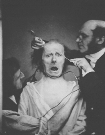
Since the early experiments of Luigi Galvani and Alessandro Volta (see insets), the use of electrical conductors to transmit charge into and out of biological systems to affect biological processes has been the source of great scientific interest. This has inspired many to explore the possible use of electrical stimulation in promoting positive health outcomes. Some of the earliest examples of using electrical stimulation in a controlled manner to achieve specific clinical outcomes were developed by Guillaume-Benjamin-Amand Duchenne (see inset) (Figure 1.1). Duchenne's interests in physiognomic esthetics of facial expression led to the definition of neural conduction pathways. During this important period in the history of science, Duchenne developed nerve conduction tests using electrical stimulation and performed pioneering studies of the manner in which nerve lesions could be diagnosed and possibly treated.
Figure 1.1 Demonstration of the mechanics of facial expression using electrical stimulation. The test subject, a cobbler by trade and a patient of Duchenne's, is “faradized” by Duchenne (right) and his assistant (left). The stimulation was applied to the cobbler's mimetic (facial) muscles and caused a change in his facial expression.
To date, medical bionic devices have been largely targeted toward the primary “excitable cell” systems, muscle, and nerve, whose functions are inherently capable of being modulated by electrical stimulation. There have also been numerous studies of the use of electrical stimulation for bone regrowth and wound healing. The effects of electrical stimulation are thought to be promoted through the induced movement of positive and negative charged ions in opposite directions (polarization) across cells and tissues that activates sensory or motor functions [2].
Landmark developments such as the artificial heart in 1957 (Kolff and Akutsu) [3, 4] the external (1956) [5] and then implantable (1958) [6] cardiac pacemaker; the artificial vision system (1978) [7]; the cochlear implant (1978) [8, 9] deep brain stimulation (DBS) electrodes (1987) [10]; and, more recently, electroprosthetic limbs [11] are now being used along with a broad spectrum of parallel developmental projects that aim to alleviate human afflictions.
 Luigi Galvani was born 9 September, 1737, in Bologna, Italy. He was educated at Bologna's medical school and in 1762 was appointed as a public lecturer in Anatomy. In 1791, he published the “Commentary on the Effect of Electricity on Muscular Motion” in the seventh volume of the Proceedings of the Institute of Sciences at Bologna.
 Alessandro Volta was born 18 February 1745, in Como, Italy. He was appointed as a Professor of Physics at the Royal School of Como. Around 1790, Volta took an interest in the “animal electricity” discovered by Galvani. Volta built on this experimental observation, replacing the frog's legs with a more traditional electrolyte to create the world's first galvanic cell and subsequently the battery. Volta also had an interest in things pertaining to medical bionics. He recorded an experiment wherein he placed metal rods attached to an active electrode circuit into his ears and reported a sound similar to boiling water.
 Guillaume-Benjamin-Amand Duchenne (de Boulogne) was born 17 September 1806, in Boulogne-sur-Mer, France. Duchenne was a French neurologist who followed on from Galvani's research, making seminal contributions to the clinical area of muscle electrophysiology.
 Graeme Milborne Clark was born 16 August, 1935, in Camden, Australia. He studied medicine at the University of Sydney and continued his studies in general surgery at the Royal College of Surgeons, Edinburgh.
 Alan MacDiarmid was born in Masterton, New Zealand, on 14 April, 1927. He developed an interest in chemistry at around age 10 and taught himself from one of his father's textbooks. Formally educated at Hutt Valley High School and Victoria University in Wellington, New Zealand, MacDiarmid obtained his first Ph.D. degree from the University of Wisconsin-Madison in 1953. A second Ph.D. degree was awarded to him from Cambridge, United Kingdom, in 1955.
Advances in medical bionics technology are dependent on eliciting precise control of the electrical energy to deliver beneficial health outcomes. The advent of carbon-based organic conductors, through the pioneering works of Alan MacDiarmid, Alan Heeger, and Hideki Shirakawa (see inset), now provides the platform for unprecedented possibilities by which electrical energy can be used to modulate the function of medical devices.
There are three main application paradigms where the use of organic conductors as electrodes or electrode arrays in medical bionic devices could be beneficial – where the organic polymer is used to functionally stimulate the target tissue, stimulate a regenerative event in the target tissue, or stimulate communication between the nervous system and an electronically driven prosthesis.
Electrodes may be surgically implanted within the body to record (e.g., brain activity) and/or stimulate (i.e., cardiac pacing, DBS, and bone growth) function. The specific material requirements for these electrodes will differ markedly in accordance with their proposed interaction with the tissues that they are intended to stimulate. In all instances, the conducting surface needs to be able to facilitate control of the electron flux, without the promotion of adverse effects on the implant's tissue environment. Furthermore, for some applications, the conducting surface needs to be in direct contact with the surrounding tissue, while in other applications, no direct contact is required. It is in the modulation of the interaction between the target tissue and conducting surface that nonmetallic conductors, such as OCPs and/or conducting carbon materials, are able to add value toward further optimization of electrodes [12].
Neurophysiologists have used sharpened wire metal (e.g., tungsten) electrodes for over 50 years to study brain function [13], and recently, neural probes have been fashioned from silicon [14], ceramic [15], and flexible substrates [16, 17]. However, in all cases, the surfaces from which the bioelectrical impulses are transferred between tissue (e.g., neural) and electronic circuitry remain predominantly metallic. Traditionally, the materials of choice for implantable electrodes have been based on inert metals.
The type of metal, its area of exposure, and the texture of the metal surface determine the properties of the electrodes and therefore the area of application. Activated Ir oxide has been shown to have excellent charge transfer properties (3000 C μm−2), making it the material of choice for microelectrodes, but the surface is chemically unstable [18].
To enhance the metal electrode sensitivity or increase the electrode's capacity to conduct charge for use in stimulation or sensory monitoring, the impedance must be lowered [18]. This step generally involves increasing the geometric surface area of the electrode tip, often associated with a concomitant loss in resolution or either the stimulatory or recording process. Larger area electrodes cause increased tissue damage during insertion [19] or, if required, during removal.
Platinum (Pt) has been employed in cochlear implant electrodes as well as in other functional stimulation electrodes, such as pacemakers, early DBS electrodes, and vision stimulator applications. Gold, iridium (Ir) oxide [20], and alloys of Pt and Ir have likewise been incorporated into bioelectrodes for a wide variety of applications [21–23].
The earliest report of electrical stimulation of the nervous system to elicit auditory sensations has somewhat inauspicious, yet subtly elegant, origins. In 1779, Italian physicist Volta made several discoveries of great importance relating to electricity, including the electrochemical battery. During this period (1800s), Volta argued with Galvani over Galvani's “animal electricity” postulation and famously performed an experiment on himself in which he attached batteries to two metal rods, each of which he then inserted into his ears. On closing the circuit, he described receiving a sharp jolt to the head, followed by “a kind of crackling, jerking, or bubbling as if some dough or thick stuff was boiling” [24].
Almost two centuries later, after it was reported that a deaf patient undergoing neurosurgery heard a noise in response to electrical stimulation of the auditory nerve [25], significant scientific interest focused on the possibility that hearing could be restored by electrical stimulation. This led to the first implant for stimulation of the saccular nerve in milestone experiments by Djourno and Eyries [26] who used an induction coil that connected an electrode in the inner ear with an electrode in the temporal muscle. In this elegant experiment, a second external induction coil was used to transmit signals (pulse rates between 100 and 1000 Hz) generated from a microphone. The subject was then able to accurately identify changes in signal pulse stimulus frequency, and reported a sensation of background noise as well as specific sounds resembling “the chirping of a cricket and the spinning of a roulette wheel.”
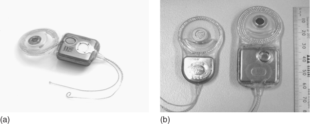
This landmark finding was the first instance in which it was specifically demonstrated that hearing could be restored in bilaterally deaf subjects by stimulation of the auditory neural pathways. Subsequent experimentation saw the parallel development of single-channel electrodes from two groups [27, 28] and their application to cochlear nerve stimulation. Resulting from this, a cochlear stimulation system developed by House [29], involved a single gold electrode that was initially adopted for production by 3M and was subsequently implanted in some 1000 people worldwide. As this device was undergoing U.S. Food and Drug Administration (FDA) approval for use in humans, Graeme Clark and coworkers [30] continued their work on the development of a multichannel implant. The multichannel cochlear implant, first implanted in a human subject in 1978, was marketed worldwide by Cochlear Pty Ltd. and has since restored hearing in more than 100 000 people worldwide. Figure 1.2 shows the integration of the main components of the cochlear implant. During its operation, sound picked up through an external microphone is encoded through a speech processor and delivered to a receiver stimulator. Resulting electrical impulses are delivered in appropriate spatiotemporal patterns to electrodes within the cochlea that stimulates the auditory neurons within the brain. The stimulatory system utilizes an array of 22 platinum microelectrodes, individually addressed through connections integrated throughout a silicon-rubber-based housing. The receiver electronics are housed in a titanium casing. The implantable component of the device was initially the receiver/stimulator package, but, recently, Cochlear developed a totally implantable cochlear implant (TICI) device in which the entire transmitter is implanted within (Figure 1.3).
Figure 1.2 Bionic ear: cochlear implant [30].
(Image obtained with permission from http://www.advancedbionics.com.)
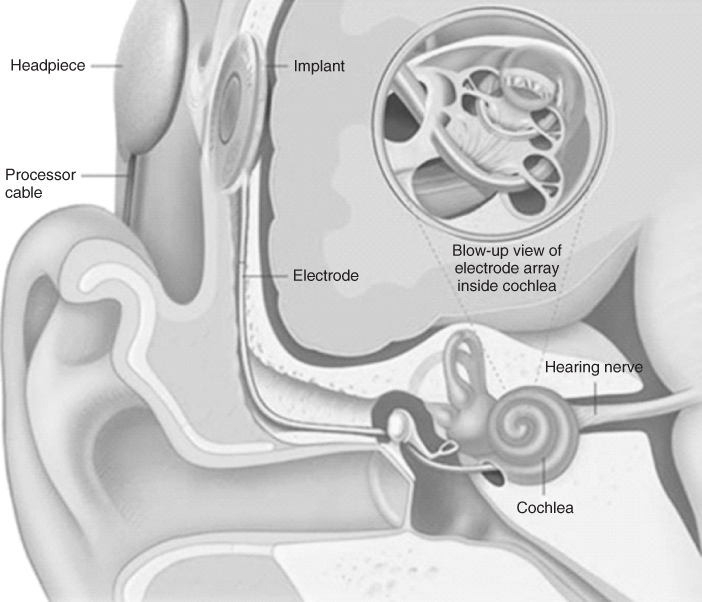
Figure 1.3 The totally implantable cochlear implant (TICI) system from Cochlear (a) is all internally implanted, including the power source and a subcutaneous microphone. (b) The TICI system (right device) compared to the 22-electrode “standard” cochlear implant (left device).
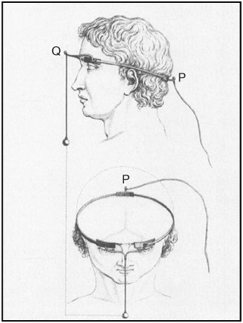
In 1755, some 36 years before Galvani communicated his “animal electricity” theory, the French chemist and physician Charles le Roy used a Leyden jar capacitor to noninvasively apply transcranial electrical stimulation to the head of a 21-year-old blind patient in the hope that this would restore the man's vision [31–33]. In what may be the first known example of a therapeutic bioelectrode system, three electrodes were anatomically aligned, two juxtaposed to the supraorbital ridges (Q in Figure 1.4) and one on the occupant (P in Figure 1.4), to stimulate the primary visual nerve tracts [32, 33]. The electrodes were connected by brass or iron wire and wound two to three times around the head; a wire leading to the right leg and a Leyden jar capacitor completed the circuit. While the patient reported sensation of phosphenes (percepts of light) after being shocked, he nevertheless remained blind despite several subsequent applications of the procedure.
Figure 1.4 Charles le Roy's electrical stimulation experiment to restore vision.
Despite these early heroic forays into attempting to restore vision using electrical stimulation, no successful strategies, let alone therapies, emerged until the mid-twentieth century. Nevertheless, in terms of medical bionic developments, it is within the field of vision bionics that the most intensive research activity has occurred.
In the present day, significant advancement in knowledge on the biological and engineering prerequisites for the restoration of vision has resulted in the evolution of multiple approaches that can provide significantly greater scope for success than has been attainable in the past. Collectively, these approaches provide unprecedented choice as to where along the optic neural circuitry an electrode may be applied to effect visual percepts in blind subjects. Such choices currently being explored include stimulation of existing functional neurons in the retina [34–36] or direct stimulation of the optic nerve [23, 37, 38]. In cases where these regions are functionally compromised, the neurons within the visual cortex of the central nervous system (CNS) [39, 40] provide another target of interest.
Current strategies for restoring lost vision by electrical stimulation of visual neural pathways within the visual cortex involve more complex electrode configurations ranging from a four-contact single cuff [37], a relatively thrifty (up to 16 electrodes) multielectrode array (MEA) [23] for optic nerve stimulation, and “higher order” silicon-based MEAs (initially an 81-electrode array) [41] for cortical stimulation and cover several target foci along the neuroptic pathway.
These well-established approaches are bolstered by ongoing developmental strategies, such as suprachoroidal transretinal stimulation with electrodes between the sclera and the vitreous chamber [42], that have yet to be applied to human subjects.
In some cases of blindness, the neural deficit occurs at the start of the neuroptic pathway. Conditions such as retinitis pigmentosa and age-related macular degeneration affect the retina, but the cones and rods that transfer visual signaling to the CNS are left intact. These conditions require (arguably) the least neuroinvasive prosthetic interventions and, as such, bionic prosthetics for such conditions focus on electrical stimulation at the retina.
Numerous animal studies indicating that the visual cortex could be stimulated in the absence of photoreceptors and characterizing the currents required to stimulate retinal ganglia [43–45] inspired scientific interest in the possibility that epiretinal (i.e., on the retina) electrical stimulation could restore vision in conditions where the point of neurological damage or deficit was the retina itself. This was confirmed in subsequent human studies, which demonstrated that stimulation of the retinal surface of blind subjects was able to generate phosphenes [46]. These phosphenes were able to be spatially characterized, such that the visual perception was sufficient for the blind subject to perceive movement after the implant. Follow-up experiments showed vast improvements on the earlier results, allowing the individual to perceive shapes [47]. This landmark finding spurred substantial research activity in this area, during which time much improvement on the initial application of the concept was achieved [48, 49].
There are five major initiatives to deliver retinal prostheses to blind humans. Three of these programs (Second Sight Argus, EPI-RET, and Intelligent Medical Implants) utilize epiretinal approaches, while the remaining two (Boston Retinal Implant and Retina Implant AG) adopt subretinal approaches. All of these systems generally utilize thin-film MEAs, with the electrodes made from platinum, platinum/iridium, iridium oxide, or titanium nitride [50].
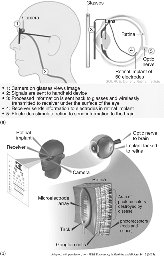
One system, developed as part of the United States' Department of Energy Artificial Retina Project, consisted of a small camera and transmitter mounted in spectacles that communicated visual fields to the brain via an implanted receiver electrically stimulating a 16-channel MEA (initially) attached to the retina. The system was powered by a battery pack worn on the belt via a wireless microprocessor (Figure 1.5).
Figure 1.5 US Department of Energy Artificial Vision System: (a) schematic of the system components and (b) schematic of the system's function to stimulate neurons in the retina.
(Adapted from Chader and coworkers [51].)
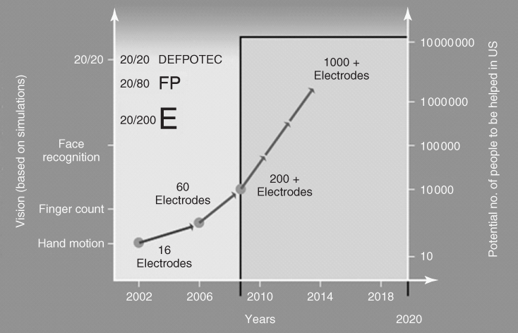
In 2002, the Argus I (a 16-channel MEA) was implanted onto the retina of a 77-year-old blind man as part of a microelectronic artificial vision system (Figure 1.6a,b). As a result, the man, who had been blind for the past 50 years, was able to perceive motion, distinguish objects, and distinguish patterns of light and dark [52]. Between 2002 and 2009, a further five people were implanted as part of the first phase of clinical trials with the Argus I device. Since 2009, some 30 legally blind subjects have been implanted with a second-generation device utilizing a 60-electrode MEA (Argus II) [51] as part of phase II/III clinical trials sponsored by Second Sight Medical Products Inc. The ultimate goal is to design a device that contains hundreds to more than a thousand microelectrodes (Figure 1.7). If successful, this device will help restore vision to people blinded by retinal disease, and enable reading, unaided mobility, and facial recognition.
Figure 1.6 The implanted electrode array with electrode positions is shown two weeks after surgical implantation on the retina (a). The black arrow indicates a clinical reference point. Representation of the percepts elicited by stimulation of the electrodes relative to the implanted subject's visual field (b). Not all electrodes are included because of issues with the threshold current required to elicit a response at these initial stages of the implant's application. Picture (c) and schematic (d) of the Boston Retinal Implant System for Restoration of Vision.
(Image adapted with permission from Humayun and coworkers [52].)
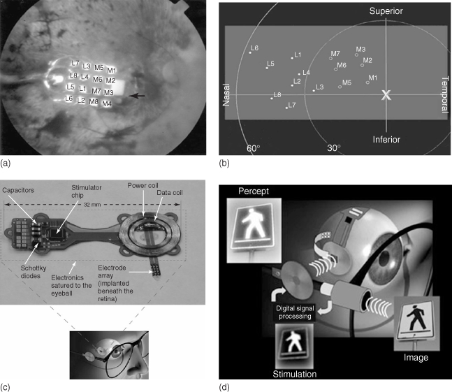
Figure 1.7 Milestone map for the US DOE's Artificial Retina Program.
(Adapted with permission from the Department of Energy newsletter, 5 January 2008; taken from Chader and coworkers [51].)
The Boston Retinal Implant Project is focused on developing a system for restoration of vision and is based on a visual prosthesis that receives two types of input, namely, (i) information about the visual scene (“visual signal”) and (ii) power and data to run the electronics and stimulate the retina in order to generate the corresponding visual image (Figure 1.6c,d). This system uses wireless communication utilizing radiofrequency (RF) to transmit data and power to receiving coils located on the prosthesis. Electrical current passing from individual electrodes (implanted within the retina) stimulate cells in the appropriate areas of the retina corresponding to the features in the visual scene. The results of initial trials were encouraging although the prosthesis has only been trialed on six human patients in a controlled surgical environment, with each trial lasting several hours. These tests showed that the stimulating electrode placed over the retina was able to stimulate enough retinal nerves in the patients who had been legally blind for decades, so they were able to see relatively small spots of light (i.e., like a “pea” as if viewed at arm's length). Occasionally, they were able to distinguish two spots of light from one another and “see” a line.
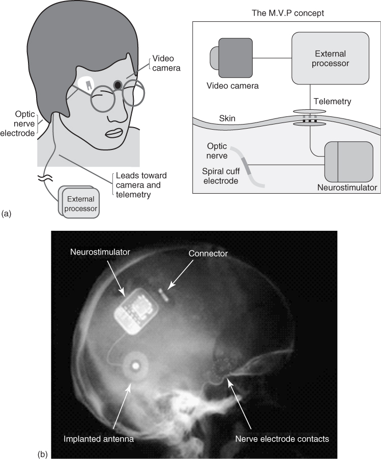
Emanating from the Université Catholique de Louvain (Brussels, Belgium), a four-contact cuff electrode was used by Claude Veraart for stimulation of the optic nerve and implanted into a 52-year-old woman who had lost her vision as a result of retinitis pigmentosa [53]. In this application, the intracranially implanted electrode was connected through the skull and skin to an extracranial stimulator. Phosphenes were generated by mono- and bipolar electrical stimulation paradigms. This continues to be developed as the Microsystems Visual Prosthesis (MiViP) system (Figure 1.8) by Veraart and colleagues [54] and is the only system that has reported any color modulations associated with the stimulation.
Figure 1.8 (a) Schematic of visual prosthesis for optic nerve stimulation using a four-channel self-adjusting cuff electrode and (b) X-ray image of the system in place in a blind human.
(Adapted from Veraart and coworkers [54].)
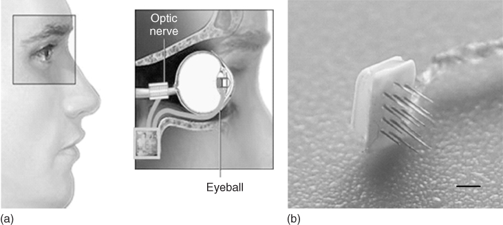
In another approach to optic nerve stimulation, the C-Sight program [23] has adopted the use of penetrating platinum/iridium MEAs by which to stimulate the optic nerve. In this adaptation, the vision capture device will be implanted into the subject's eye, rather than using spectacles with an inbuilt camera/lens (Figure 1.9).
Figure 1.9 Schematic of visual prosthesis for optic nerve stimulation using microelectrode arrays from the C-Sight program (a), with 16 probes of 0.2 mm in length (b) scale bar is 1 mm.
(Adapted from Boockvar and coworkers [21].)
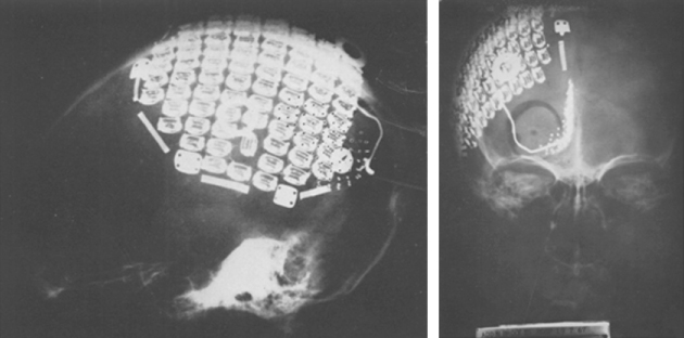
After research identified that stimulation of the calcarine cortex produced visual sensations in humans with nonfunctional eyes in 1967, Brindley and Lewin [41] implanted an 81-electrode array (platinum encased in silicon) of subdural nonpenetrating electrodes over the occipital cortex of a 52-year-old woman who lost her vision because of retinal detachment (Figure 1.10). In these experiments, which laid the foundation for cortical electrical stimulation to restore lost vision, approximately half of the implanted electrodes were functional and produced phosphenes within the subject's visual field.
Figure 1.10 The 81-electrode array implanted by Brindley and Lewin.
(Adapted from Brindley and Levin [41].)
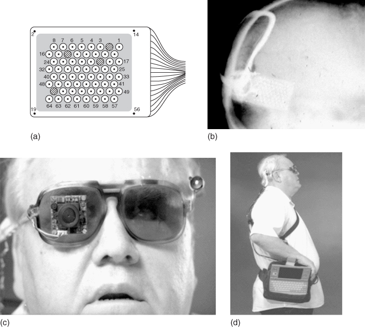
Indeed, it was this electrode/stimulation methodology that ultimately led to the first reported case of “useful” sight in blind humans via a 64-electrode (platinum encased in a teflon substrate) intracranial MEA system developed by William Dobelle et al. [7]. After the implant, Dobelle's subjects were able to read “Braille” images perceived as phosphenes that were reproducibly controlled according to the combination of electrodes stimulated. Although this approach increased the speed with which Braille could be read, it was seen only as a transitional indicator that this technology could provide “useful” sight in the blind and was not adopted for common use.
Dobelle's cortical MEA was also implanted into two humans, one who was able to “see” sufficiently to navigate effectively by sight [55] and one who never perceived phosphenes (Figure 1.11). Nevertheless, while both these people sustained their implants for 20 years without issue, the functioning of the former individual's electrode array eventually deteriorated, requiring removal. This need for a device to be accepted by the surrounding tissues perhaps highlights one of the key challenges facing electrode implants in the human body.
Figure 1.11 Dobelle's sub-cranial, nonpenetrating cortical implant (a,b) was the first prosthetic device that restored lost “useful” vision in a human subject (c,d).
(Adapted from Dobelle [55].)
Utah Artificial Vision Systems will be designed to essentially transform light from within an incident field of vision captured by a camera and integrate the light, via a pair of spectacles, into electrical signals. These electrical signals will then be translated by a signal processor into electrical stimulation patterns for the visual cortex, that will, in turn, elicit ordered phosphene percepts (25 × 25, or 625 points of stimulation) [56] sufficient to give the sensation of “seeing” objects in the field of “sight.” The application of the Utah Electrode Array (UEA) (Figure 1.12) within this system will be to deliver the electrical stimulation to the visual cortex and the current 100 probe configuration will be further developed into a 625 microelectrode configuration [57].
Figure 1.12 (a) The Utah Electrode Array (UEA). (b) The Utah Slanted Electrode Array (USEA). Each of the electrodes in these arrays is made of insulated (silicon) gold wires tipped with platinum (initially) or iridium oxide. They can be implanted in regions of the central or peripheral nervous systems. (c) Schema for cortical stimulation using the UEA in the Utah Artificial Vision System.
(Adapted from Normann [57].)

The UEA and Utah Slanted Electrode Array (USEA) consist of gold wires insulated with silicon, tipped with platinum, or, more recently, iridium oxide. Each of the silicon probes are 80 μm in diameter at their base, around 1.5 mm in length (UEA) and spaced from each other at distances of 0.4 mm. The slanted version of the array differs from the UEA by a progressive gradation in the length of the individual probes from 0.5 to 1.5 mm in length (Figure 1.12), primarily for use in peripheral nerves. Essentially, the UEA systems have been designed to integrate with neural tissue, which raises the important question (relevant to any other similar implantable electrode array) as to how they can be removed if they show signs of failure. In particular, how the removal of such electrodes will affect the function of that tissue into which they had been implanted is a major consideration that still needs to be addressed within the medical bionics area.
Within the backdrop of enormous pressure driving rapid technological improvement, significant advances have been made in all aspects of artificial vision technologies. It is at the point of transaction between the neural and electronic circuitry, for example, the electrode/neural tissue interface, that perhaps the most rapid development has taken place since the 1950s. There are proposals to expand Dobelle's original 68-electrode MEA system to 516 electrodes [55] and, as mentioned, the UEA system to at least 625 microelectrodes (the minimum electrode number sufficient to allow reading and effective navigation) [58]. The Michigan Electrode Array has already achieved as many as 1024 microelectrodes [59, 60] but is, at present, limited by the spatial requirements of the tissue into which it is intended to be implanted and availability of sufficient wiring to address each electrode. It is thus not surprising that neuroelectrode fabrication technologies and protocols developed in the highly dynamic area of vision restoration have provided a technological platform for the development of many other neuroprosthetic applications.
MEA systems designed to interact with excitable cell systems will inevitably undergo further development to incorporate significantly greater numbers of individual electrodes by which to stimulate discrete cellular entities. These designs will undoubtedly enhance the resolution of neurostimulation, and/or monitoring signals, and will better meet the challenges of the environment into which they are to be implanted. In view of the major advancements in the spatial resolution with which electrodes can interface with the human nervous system, concurrent technologies in connecting and acquiring the neural signals with the electronic circuitry will also need to improve [61].
With a few exceptions (e.g., DBS in Parkinson's disease, vagal nerve stimulation (VNS)), in most applications of CNS stimulation and monitoring, single electrodes generally provide limited therapeutic opportunities. There are significant advantages afforded by high-density/resolution interfacing between the electrodes and neurons. This is particularly evident for human vision studies that have been a driving force behind the design of highly engineered MEAs, which are much smaller, precise, and effective in their ability to address the tissue, hence improving their functionality.
The elegance of current cortical stimulation MEA designs is exemplified by the UEA [62] and USEA [63] described above. The UEA design accommodates applications beyond the restoration of vision, such as connection of volitional thought toward movement with electronic prosthetic limbs [64]. The first step where the connection of thought with electronic prostheses was successfully achieved was in humans with tetraplegic spinal cord injuries [65]. Using the Neuroport® Array (Cyberkinetics Neurotechnology Systems Inc., Foxborough, MA), a commercial version of the UEA was implanted in patients who then demonstrated their ability to move cursors on a computer screen. This initially promising result has been extended in a recent initiative supported by the Defense Advanced Research Projects Agency (DARPA) to connect volitional movement thoughts with electronic prosthetic limbs that may even be able to deliver touch sensation to people who have had one or more limbs amputated.
The versatile “modular” thin-film three-dimensional array (Michigan 3D Electrode Array) consisting of individual modules containing 16 probes with 8 electrodes per probe (total of 128 electrodes per module) that can be attached to each other to form 3D arrays, containing as many as 1028 electrodes [60] (Figure 1.13), could likewise be applied for prosthetic limb control.
Figure 1.13 The Michigan 3D electrode array. A 1028-electrode, 12-channel array (a) and individual probe tip (b).
(Adapted from Wise and coworkers [59].)
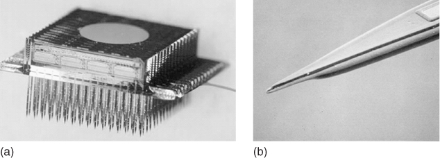
This “many birds with few stones” approach and capability, demonstrated initially by the UEA but nevertheless applicable to most of the existing electrode systems, delivers major advantages in hugely expanding the scope of medical bionics applications able to be effectively targeted by a relatively few devices. This broad applicability to medical bionic devices thus significantly reduces the research and developmental costs required to translate a device into the clinical setting.
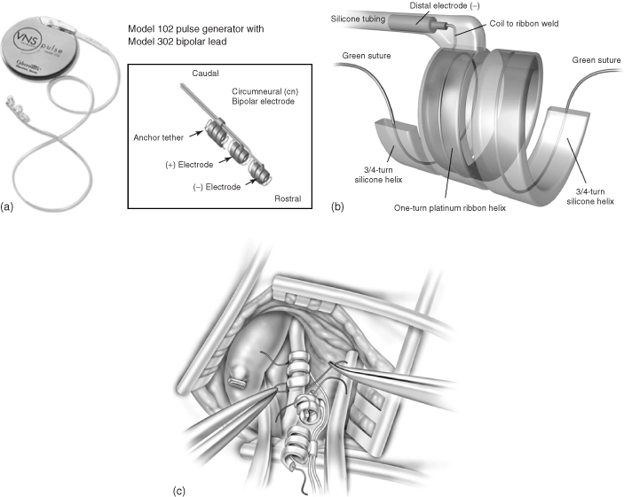
Since the earliest observations that stimulation of the vagus nerve (also known as the pneumogastric nerve, cranial nerve X, the Wanderer, or the Rambler) evoked responses in the ventroposterior complex and the thalamus [66], there has been increasing clinical scientific interest in using this approach for controlling epileptic seizures. This was ultimately confirmed in experiments by Zabara who was able to abort seizures in a strychnine dog model of epilepsy in 1985 [67]. Three years later, five patients with programmable “NeuroCybernetics Prosthesis” stimulators produced by Cyberonics were implanted in humans as part of two pilot studies [68]. These studies showed that electrical stimulation of the vagal nerve led to a 46% mean reduction in the seizures experienced by the tested subjects. After a decade of animal experimentation and clinical trials, in 1997 the vagal nerve stimulator received regulatory approval from the US FDA for use in people older than 12 years of age who are affected by refractory partial-onset seizures. All VNS systems are similar in design. For example, the Cyberonics “NeuroCybernetics Prosthesis” (Figure 1.14) consists of a titanium-encased generator powered by a lithium battery that is implanted within the chest cavity [69]. A lead wire system with platinum–iridium electrodes in a triple coil cuff configuration is wound around the vagus nerve, where it is sutured in place (Figure 1.14c). To date, more than 30 000 people have been treated with VNS [70].
Figure 1.14 NeuroCybernetics vagal nerve stimulator system with a 102 pulse generator and 302 bipolar cuff electrode (a). (b) Diagram of the distal electrode, and (c) its implantation around the vagus nerve.
(Adapted from Santos and [69] and Nemeroff and coworkers [70].)
During early VNS trials, observations were made that the moods of epileptic test subjects improved with stimulation. This led to a potential role for VNS therapy in depression. A focused study of depression symptom severity rating scales in subjects with epilepsy confirmed that VNS therapy was directly associated with positive mood changes [71, 72]. In addition, there was physiological evidence of reductions in the metabolic activity in CNS regions (i.e., amygdala, hippocampus, cingulate gyrus) associated with mood [73]. However, while science indicates benefits in using VNS to treat unresponsive depression, it is generally accepted within the field that there is still much to be learned before VNS is used to treat a depressive disorder. VNS has also been reported to reduce experimentally induced pain [74], and migraine [75], although again, through largely undefined pathways.
Devices used for pain management utilize electrical impulses aimed at blocking nociception (pain). For example, surgical placement of epidural electrodes along the dorsal columns allows spinal cord stimulation. This approach is hypothesized to work through the gate-control theory of Wall and Melzack [76], whereby the strategically placed electrodes stimulate the dorsal columns to inhibit the incoming nociceptive input via the so-called A delta or C fibers in the spinal cord.
Cardiac pacing involves the implantation of a medical device called a pacemaker (or artificial pacemaker, so as not to be confused with the heart's natural pacemaker), which uses electrical impulses delivered by electrodes to promote timed contraction of heart muscles and thus regulate the beating of the heart (Figure 1.15).
Figure 1.15 Image shows the location of the leads and electronics (including power source) for the implantable artificial pacemaker.
(Image obtained with permission from www.education.science-thi.org.)
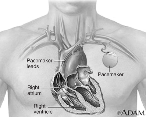
A cardiac pacing lead is just a simple cable that connects the pulse generator to the heart. The size, longevity, and features of the pulse generator and the patient's safety depend on the performance of the lead. The leads are generally thin, insulated wires that are designed to carry electricity between the battery and heart. Depending on the type of pacemaker, it will contain either a single lead for single-chamber pacemakers, or two leads for dual-chamber pacemakers. With the constant beating of the heart, these wires are chronically flexed and hence must be resistant to fracture. There are many styles of leads available, with primary design differences found at the exposed end. Many of the leads have a screw-in tip, which helps anchor them to the inner wall of the heart. Pacing leads typically have an electrode pair at the tip comprising a tip electrode and a ring (or band) electrode, both of which are used for sensing intracranial electrical activity and administering low-voltage pacing stimuli (Figure 1.16). These pacing electrodes are commonly made of platinum–iridium (Pt alloyed with 10–20% Ir) [77].
Figure 1.16 Orthofix external bone growth stimulator.
(Image obtained with permission from www.orthofix.com.)
The pacemaker must assure that the heart will contract with each stimulus. Thus, the pacemaker must deliver a controlled pulse of voltage with sufficient duration to assist the patient to cope with any minute-to-minute variations that may occur in their heart beat during daily life. At the same time, it is necessary for the device to use minimal current to maintain battery longevity. The most common approaches to reliably deliver stimuli, within adequate safety parameters while decreasing the current drained from the battery, have traditionally centered around electrode size and material, surface structure and shape and, more recently, glucocorticosteroid sustained release [78].
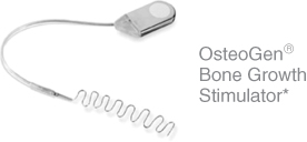
The use of electrical bone growth stimulation (EBGS) is an accepted clinical approach to promote bone growth and heal fractures. In the early days of electrically induced bone growth, a range of metal electrode materials were investigated. In 1982, Spadaro [79] employed six different metallic cathode materials in a rabbit medullary canal and applied cathodic currents of 0.02 and 0.2μA mm−2 for 21 days. This stimulation resulted in quantitative differences in new bone growth. That is, platinum, cobalt-chrome (F-90), and silver led to more bone relative to control implants at the lower geometric current density, while stainless steel (316L) and titanium cathodes were more effective at the higher current. On average, there was a significant increase (46–48%) in new bone formation for the active versus control implants, for either current level. In today's market, the electrode material of choice used for internal stimulation is titanium.
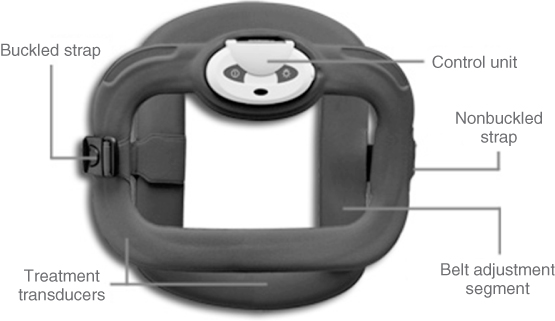
There are three types of EBGS available:
Figure 1.17 OsteoGen internal bone growth stimulator.
(Image obtained with permission from www.biomet.com.)
One of the most commonly used external stimulating bionic devices on the market today is the transcutaneous electrical nerve stimulation (TENS) system (Figure 1.18aFigure 1.18b