

Table of Contents
Related Titles
Title page
Copyright page
Preface to the Second Edition
Preface to the First Edition
1: Cements and Cement Paste
1.1 Portland Cement and Hydration Reactions
1.2 Porosity and Transport Processes
1.3 Blended Cements
1.4 Common Cements
1.5 Other Types of Cement
2: Transport Processes in Concrete
2.1 Composition of Pore Solution and Water Content
2.2 Diffusion
2.3 Capillary Suction
2.4 Permeation
2.5 Migration
2.6 Mechanisms and Significant Parameters
3: Degradation of Concrete
3.1 Freeze–Thaw Attack
3.2 Attack by Acids and Pure Water
3.3 Sulfate Attack
3.4 Alkali Silica Reaction
3.5 Attack by Seawater
4: General Aspects
4.1 Initiation and Propagation of Corrosion
4.2 Corrosion Rate
4.3 Consequences
4.4 Behavior of Other Metals
5: Carbonation-Induced Corrosion
5.1 Carbonation of Concrete
5.2 Initiation Time
5.3 Corrosion Rate
6: Chloride-Induced Corrosion
6.1 Pitting Corrosion
6.2 Corrosion Initiation
6.3 Corrosion Rate
7: Electrochemical Aspects
7.1 Electrochemical Mechanism of Corrosion
7.2 Noncarbonated Concrete without Chlorides
7.3 Carbonated Concrete
7.4 Concrete Containing Chlorides
7.5 Structures under Cathodic or Anodic Polarization
8: Macrocells
8.1 Structures Exposed to the Atmosphere
8.2 Buried Structures and Immersed Structures
8.3 Electrochemical Aspects
8.4 Modeling of Macrocells
9: Stray-Current-Induced Corrosion
9.1 DC Stray Current
9.2 AC Stray Current
9.3 High-Strength Steel
9.4 Fiber-Reinforced Concrete
9.5 Inspection
9.6 Protection from Stray Current
10: Hydrogen-Induced Stress Corrosion Cracking
10.1 Stress Corrosion Cracking (SCC)
10.2 Failure under Service of High-Strength Steel
10.3 Metallurgical, Mechanical and Load Conditions
10.4 Environmental Conditions
10.5 Hydrogen Generated during Operation
10.6 Hydrogen Generated before Ducts Are Filled
10.7 Protection of Prestressing Steel
11: Design for Durability
11.1 Factors Affecting Durability
11.2 Approaches to Service-Life Modeling
11.3 The Approach of the European Standards
11.4 The fib Model Code for Service-Life Design for Chloride-Induced Corrosion
11.5 Other Methods
11.6 Additional Protection Measures
11.7 Costs
12: Concrete Technology for Corrosion Prevention
12.1 Constituents of Concrete
12.2 Properties of Fresh and Hardened Concrete
12.3 Requirements for Concrete and Mix Design
12.4 Concrete Production
12.5 Design Details
12.6 Concrete with Special Properties
13: Corrosion Inhibitors
13.1 Mechanism of Corrosion Inhibitors
13.2 Mode of Action of Corrosion Inhibitors
13.3 Corrosion Inhibitors to Prevent or Delay Corrosion Initiation
13.4 Corrosion Inhibitors to Reduce the Propagation Rate of Corrosion
13.5 Transport of the Inhibitor into Mortar or Concrete
13.6 Field Tests and Experience with Corrosion Inhibitors
13.7 Critical Evaluation of Corrosion Inhibitors
13.8 Effectiveness of Corrosion Inhibitors
14: Surface Protection Systems
14.1 General Remarks
14.2 Organic Coatings
14.3 Hydrophobic Treatment
14.4 Treatments That Block Pores
14.5 Cementitious Coatings and Layers
14.6 Concluding Remarks on Effectiveness and Durability of Surface Protection Systems
15: Corrosion-Resistant Reinforcement
15.1 Steel for Reinforced and Prestressed Concrete
15.2 Stainless Steel Rebars
15.3 Galvanized Steel Rebars
15.4 Epoxy-Coated Rebars
16: Inspection and Condition Assessment
16.1 Visual Inspection and Cover Depth
16.2 Electrochemical Inspection Techniques
16.3 Analysis of Concrete
17: Monitoring
17.1 Introduction
17.2 Monitoring with Nonelectrochemical Sensors
17.3 Monitoring with Electrochemical Sensors
17.4 Critical Factors
17.5 On the Way to “Smart Structures”
17.6 Structural Health Monitoring
18: Principles and Methods for Repair
18.1 Approach to Repair
18.2 Overview of Repair Methods for Carbonated Structures
18.3 Overview of Repair Methods for Chloride-Contaminated Structures
18.4 Design, Requirements, Execution and Control of Repair Works
19: Conventional Repair
19.1 Assessment of the Condition of the Structure
19.2 Removal of Concrete
19.3 Preparation of Reinforcement
19.4 Application of Repair Material
19.5 Additional Protection
19.6 Strengthening
20: Electrochemical Techniques
20.1 Development of the Techniques
20.2 Effects of the Circulation of Current
20.3 Cathodic Protection and Cathodic Prevention
20.4 Electrochemical Chloride Extraction and Realkalization
Index
Related Titles
Sharma, S. K. (ed.)
Green Corrosion Chemistry and Engineering
Opportunities and Challenges With a Foreword by Nabuk Okon Eddy
2012
ISBN: 978-3-527-32930-4
Schütze, M., Wieser, D., Bender, R. (eds.)
Corrosion Resistance of Aluminium and Aluminium Alloys
2010
ISBN: 978-3-527-33001-0
Bernold, L. E., AbouRizk, S. M.
Managing Performance in Construction
2010
ISBN: 978-0-470-17164-6
Krzyzanowski, M., Beynon, J. H., Farrugia, D. C. J.
Oxide Scale Behavior in High Temperature Metal Processing
2010
ISBN: 978-3-527-32518-4
Revie, R. W.
Corrosion and Corrosion Control, Fourth Edition
2010
ISBN: 978-0-470-65366-1
Kreysa, G., Schütze, M. (eds.)
Corrosion Handbook – Corrosive Agents and Their Interaction with Materials
13 Volume Set
2009
ISBN: 978-3-527-31217-7
Galambos, T. V., Surovek, A. E.
Structural Stability of Steel
Concepts and Applications for Structural Engineers
2009
ISBN: 978-0-470-03778-2
Heimann, R. B.
Plasma Spray Coating
Principles and Applications
2008
ISBN: 978-3-527-32050-9
Geschwindner, L. F.
Unified Design of Steel Structures
2008
ISBN: 978-0-471-47558-3
Roberge, P. R., Revie, R. W.
Corrosion Inspection and Monitoring
2007
ISBN: 978-0-471-74248-7

The Authors
Prof. Luca Bertolini
Politecnico di Milano
Department of Chemistry, Materials, and Chemical Engineering “G. Natta”
Piazza Leonardo da Vinci 32
20133 Milano
Italy
Prof. Bernhard Elsener
ETH Zürich
Institute for Building Materials
ETH Hönggerberg
8093 Zürich
Switzerland
Dr. Elena Redaelli
Politecnico di Milano
Department of Chemistry, Materials, and Chemical Engineering “G. Natta”
Piazza Leonardo da Vinci 32
20133 Milano
Italy
Prof. Rob Polder
TNO Technical Sciences/Built Environment
P.O. Box 49
2600 AA Delft
The Netherlands
Delft University of Technology
P.O. Box 5048
2600 CA Delft
The Netherlands
Cover: The picture used on the cover is a painting on a titanium surface, created by Prof. Pietro Pedeferri. We thank his heirs for the kind permission to use this work of art.
All books published by Wiley-VCH are carefully produced. Nevertheless, authors, editors, and publisher do not warrant the information contained in these books, including this book, to be free of errors. Readers are advised to keep in mind that statements, data, illustrations, procedural details or other items may inadvertently be inaccurate.
Library of Congress Card No.: applied for
British Library Cataloguing-in-Publication Data
A catalogue record for this book is available from the British Library.
Bibliographic information published by the Deutsche Nationalbibliothek
The Deutsche Nationalbibliothek lists this publication in the Deutsche Nationalbibliografie; detailed bibliographic data are available on the Internet at <http://dnb.d-nb.de>.
© 2013 Wiley-VCH Verlag GmbH & Co. KGaA, Boschstr. 12, 69469 Weinheim, Germany
All rights reserved (including those of translation into other languages). No part of this book may be reproduced in any form – by photoprinting, microfilm, or any other means – nor transmitted or translated into a machine language without written permission from the publishers. Registered names, trademarks, etc. used in this book, even when not specifically marked as such, are not to be considered unprotected by law.
Composition Toppan Best-set Premedia Ltd., Hong Kong
Cover Design Bluesea Design, Simone Benjamin, McLeese Lake, Canada
Print ISBN: 978-3-527-33146-8
ePDF ISBN: 978-3-527-65172-6
ePub ISBN: 978-3-527-65171-9
mobi ISBN: 978-3-527-65170-2
oBook ISBN: 978-3-527-65169-6
Preface to the Second Edition
Since this book was first published, durability of reinforced concrete structures has continued to receive worldwide interest of materials scientists and designing engineers. Although some of the open questions raised in the preface of the first edition have found reasonable explanations in the past decade, others are still unanswered and new issues have arisen. For example, the need for sustainability has, on the one hand, increased the demand for durable structures and, on the other hand, promoted the development and use of new materials with lower environmental impact whose durability properties need to be verified. The increased demand for maintaining large numbers of existing structures and prolonging their service life poses technical and economical challenges of a larger scale. At the same time, increased experience with regard to repair techniques and materials must be incorporated in asset management on the scale of, for example, road networks. Challenges for the next decade are science-based models for the prediction of service life of new and existing structures and reliable accelerated tests that are able to provide durability-related design parameters both for concrete (e.g., with regard to resistance to carbonation or chloride penetration) and for steel (e.g., relating to the chloride threshold for corrosion initiation).
In the second edition of this book, all chapters have been revised and updated with recent findings and new perspectives. The structure of the book has been maintained, so that it may serve as a reference for students and materials scientists, who may learn from the explanation of corrosion and degradation mechanisms, as well as people involved in the design, execution, and management of reinforced concrete structures, who may concentrate on the parts of the book dealing with practical aspects of assessment, monitoring, prevention, and protection techniques.
With this second edition we also have a new co-author, Elena Redaelli, but, sadly, we lost Pietro Pedeferri, who passed away on 3 December 2008. Pietro strongly wanted the first edition of this book, and he was the driving force for its realization. He dedicated his life to the study of electrochemistry and corrosion science and technology, making important contributions to several aspects of corrosion and protection techniques, such as localized corrosion of stainless steels, cathodic protection, corrosion in the human body, corrosion in the oil industry, surface treatments of titanium, and corrosion and protection of steel in concrete. Corrosion of steel in concrete became a major field of interest for him in the 1980s. Looking for a durable solution to prevent corrosion of reinforcing steel in motorway bridges exposed to chloride contamination due to de-icing salt application, he proposed the technique of cathodic prevention, and in explaining the advantages of cathodic prevention over cathodic protection, he developed the graph shown in Figure 20.4, now internationally acknowledged as Pedeferri’s diagram. This graph definitely expresses Pietro’s spirit as a researcher as well as a teacher, showing that he was able to transfer in a simple, although rigorous, manner a complex matter as the way of dealing with depassivation and repassivation of steel in chloride-contaminated concrete. Pietro Pedeferri contributed to the understanding of several mechanisms involved in the corrosion behavior of steel reinforcement in concrete, and his knowledge permeates the whole book, even in this new edition.
The front cover is a tribute to Pietro Pedeferri as an artist. In fact, he was able to conjugate his research studies on the anodic oxidation of titanium with his creativity, and he developed a unique technique for electrochemical painting of titanium. Mixing acids, electrical currents, flow of liquids, and his poetic inspiration, he generated beautiful and colorful drawings.
The Authors, January 2013
Preface to the First Edition
Over the millennia, concrete prepared by the Romans using lime, pozzolana and aggregates has survived the elements, giving proof of its durability. Prestigious concrete works have been handed down to us: buildings such as the Pantheon in Rome, whose current structure was completed in 125 A.D., and also structures in marine environments have survived for over two thousand years. This provides a clear demonstration that concrete can be as durable as natural stone, provided that specific causes of degradation, such as acids or sulphates, freeze–thaw cycles, or reactive aggregates, are not present.
Today, thanks to progress made over the past few decades in the chemistry of cement and in the technology of concrete, even these causes of deterioration can be fought effectively. With an appropriate choice of materials and careful, adequately controlled preparation and placement of the mixture, it is possible to obtain concrete structures which will last in time, under a wide variety of operative conditions.
The case of reinforced concrete is somewhat different. These structures are not eternal, or nearly eternal, as was generally supposed up until the 1970s. Instead, their service life is limited precisely because of the corrosion of reinforcement. Actually, concrete provides the ideal environment for protecting embedded steel because of its alkalinity. If the design of a structure, choice of materials, composition of the mixture, and placement, compaction and curing are carried out in compliance with current standards, then concrete is, under most environmental conditions, capable of providing protection beyond the 50 years typical of the required service life of many ordinary structures, at least in temperate regions. In fact, cases of corrosion that have been identified in numerous structures within periods much shorter than those just mentioned can almost always be traced to a failure to comply to current standards or to trivial errors in manufacturing of the concrete. However, under environmental conditions of high aggressiveness (generally related to the presence of chlorides), even concrete which has been properly prepared and placed may lose its protective properties and allow corrosion of reinforcement long before 50 years have elapsed, sometimes resulting in very serious consequences.
The problem of corrosion in reinforced concrete structures is thus a very real one and must be given special consideration. It is, in fact, only since the early 1980s that research has devoted much attention to this problem. From those years on main physiological aspects related to behaviour of steel in concrete, such as the nature of the aqueous pore liquid present in the hardened concrete, the electrochemistry of steel in this environment, the mechanism of protection of steel by an oxide film, etc. have been established. Passing to the pathological side, research has explained the phenomenology and mechanisms of corrosion, established the conditions which give rise to it and the laws governing its evolution, and developed techniques for diagnosing and controlling it. In particular, it has been shown that the only circumstances that can give rise to corrosion are those when both depassivation occurs (e.g., due to carbonation or chlorides) and oxygen and humidity are present.
Several points still need to be clarified. For example: the atlas of pathological anatomy has been defined clearly with regard to corroding reinforcement, but only sketchily in relation to the surrounding concrete; the body of diagnostics allows the state of corrosion in a structure to be evaluated for the more common forms of corrosion, but is still incomplete in the case of hydrogen embrittlement in high-strength steels of prestressed structures or corrosion caused by stray current; the handbook of anticorrosionistic pharmacology includes a long list of methodologies of prevention (from inhibitors to coatings, to corrosion resistant reinforcement, to electrochemical techniques); however, their long-term effects or their possible negative side-effects are not always clearly known. Probably, the greatest shortcomings have to do with the basic aspects of corrosion. For instance, in the area of physiopathology: the species around the passive reinforcement in concrete are known, but those around corroding reinforcement are not; the influence of species on the passivity or corrosion of steel is known in qualitative terms, but very little is known of the entity of their interaction with the constituents of cement paste, and thus of their mobility in electrical fields or in various concentration gradients, in relation to the type of cement or to the characteristics of the concrete, etc.
In the field of construction, notable progress has also been achieved: the problem of corrosion, and more in general of the durability of structures in reinforced con- crete, is very seriously taken into consideration; new laws are in place and new technologies and products are available.
But the above must not lull us into a false sense of security. It is true that today there is greater sensitivity to this problem, often being the subject of conferences, seminars and publications. New rules and standards do exist, though they are perceived as compulsory, being the result of legislation. Finally, new technologies and sophisticated products are being adopted, for example in the field of repair of structures damaged by corrosion. All these aspects do not, however, in themselves eliminate the errors, often trivial, that are at the basis of most failures today, and even less are they able to solve those cases where structures operate under conditions of high aggressiveness. Substantial progress will be made, also with regard to durability, only when our current technology, based on empiricism and common sense, evolves into a technology based on a thorough knowledge of degradation processes and of methods for their control.
Education, and thus teaching in particular, has a very important role to play, not only by making professionals sensitive to the durability problem, but also by giving them the tools necessary to solve it.
We hope that this text may be useful for those who work in the field of civil and construction engineering, as well as for those involved in the area of maintenance and management of reinforced concrete structures. Its aim is to provide the knowl- edge, tools and methods to understand the phenomena of deterioration and to prevent or control them. In some sections of the text, because of our professional background, we have gone into details of some electrochemical aspects. These explanations go beyond what is strictly required in civil and construction engineering and are not essential to an understanding of the other sections.
Finally, we wish to thank the European commissions that, by promoting the cooperative actions COST 509, 521 and recently 534, gave to several European researchers the opportunity to meet, collaborate and exchange views in the field of corrosion of steel in concrete. This book was born from that cooperation. We gratefully acknowledge all friends and colleagues on COST Actions, RILEM technical committees and European Federation of Corrosion working groups for providing data, papers and, most of all, for stimulating discussion.
The Authors, November 2003
1
Cements and Cement Paste
The protection that concrete provides to the embedded steel and, more in general, its ability to withstand various types of degradation, depend on its microstructure and composition. Concrete is a composite material made of aggregates and hydrated cement paste, that is, the reaction product of the cement and the mixing water. This chapter illustrates the properties of the most utilized cements and the microstructure of hydrated cement pastes. The properties of concrete and its manufacturing are discussed in Chapter 12.
Cements are fine mineral powders that, when they are mixed with water, form a paste that sets and hardens due to hydration reactions. Portland cement is the basis for the most commonly used cements [1–5]. It is produced by grinding clinker, which is obtained by burning a suitable mixture of limestone and clay raw materials. Its main components are tricalcium and dicalcium silicates (C3S and C2S),1) the aluminate and ferroaluminate of calcium (C3A and C4AF, respectively). Gypsum ( ) is also added to clinker before grinding, to control the rate of hydration of aluminates. Table 1.1 shows the typical ranges of variation of the constituents of portland cement. Other components, such as sodium and potassium oxides, are present in small but variable amounts.
Table 1.1 Main components of portland cement and typical percentages by mass.

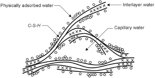
In the presence of water, the compounds of portland cement form colloidal hydrated products of very low solubility. Aluminates react first, and are mainly responsible for setting, that is, solidification of the cement paste. The hydration of C3A and C4AF, in the presence of gypsum, mainly gives rise to hydrated sulfoaluminates of calcium. Hardening of cement paste, that is, the development of strength that follows setting, is governed by the hydration of silicates. The hydration of C3S and C2S gives rise to calcium silicate hydrates forming a gel, indicated as C–S–H. It is composed of extremely small particles with a layer structure that tend to aggregate in formations a few μm in dimension, characterized by interlayer spaces of small dimensions (<2 nm) and by a large surface area (100–700 m2/g). Figure 1.1 shows a model proposed to describe this structure. Due to the high surface area, C–S–H can give considerable strength to the cement paste. Its chemical composition is not well defined since the ratio between the oxides may vary as the degree of hydration, water/cement ratio, and temperature vary (for instance the C/S ratio may vary from 1.5 to 2). However, upon complete hydration, it tends to correspond to the formula C3S2H3 usually used in stoichiometric calculations. C–S–H represents approximately 50–60% of the volume of the completely hydrated cement paste.
Figure 1.1 Feldman–Sereda model for C–S–H [2].
Hydration of calcium silicates also produces hexagonal crystals of calcium hydroxide (Ca(OH)2, portlandite). These have dimensions of the order of a few μm and occupy 20 to 25% of the volume of solids. They do not contribute to the strength of cement paste. However, Ca(OH)2, as well as NaOH and KOH, are very important with regard to protecting the reinforcement, because they cause an alkaline pH up to 13.5 in the pore liquid (Section 2.1.1).
The hydration reactions of tricalcium and dicalcium silicates can be illustrated as follows:
(1.1) 
(1.2) 
The reaction products are the same, but the proportions are different. The ratio between C–S–H and portlandite, passing from the hydration of C3S to that of C2S changes from 61/39 to 82/18, and the amount of water required for hydration from 23% to 21%. In principle, C2S should lead to a higher ultimate strength of the cement paste by producing a higher amount of C–S–H. Nevertheless, the rate of hydration is much lower for C2S compared with C3S, and the strength of cement paste after 28 days of wet curing is mainly due to C3S. Thus, the larger the amount of C3S in a portland cement, the higher the rate of hydration and strength development of its cement paste. Increasing the fineness of cement particles can also increase the rate of hydration. The reactions leading to hydration of portland cement are exothermic; hence increasing the rate of hydration also increases the rate of generation of heat of hydration.
The cement paste formed by the hydration reactions contains interconnected pores of different sizes, as shown in Figure 1.2. Although the classification of concrete porosity is quite a complex matter [6], for the purposes of this book pores can be roughly divided into air voids, capillary pores and gel pores. The interlayer spacing within C–S–H (gel pores) have dimensions ranging from a few fractions of a nm to several nm. These essentially do not affect the durability of concrete and its protection of the reinforcement because they are too small to allow significant transport of aggressive species. The capillary pores are the voids not filled by the solid products of hydration within the hardened cement paste. They have dimensions of 10 to 50 nm if the cement paste is well hydrated and produced using low water/cement ratios (w/c), but can reach up to 3–5 μm if the concrete is made using high w/c ratios or it is not well hydrated. Larger pores of dimensions of up to a few mm are the result of the air entrapped during mixing and not removed by vibration of fresh concrete. Air bubbles with diameter of about 0.05–0.2 mm may also be introduced in the cement paste intentionally by means of air-entraining admixtures, so as to produce resistance to freeze–thaw cycles (Section 3.1.3). Both capillary pores and entrapped air are relevant to the durability of concrete and its protection of the rebars, since they determine the resistance to the penetration of aggressive species. The main factors affecting the capillary porosity, that is, water/cement ratio, curing, and type of binder, will be briefly analyzed in the following sections. Entrapped air can be reduced by providing adequate workability to the fresh concrete and proper compaction; this is dealt with in Chapter 12.
Figure 1.2 Dimensional range of solids and pores in hydrated cement paste [3].

The water/cement ratio, that is, the ratio between mass of mixing water and mass of cement, and curing have a major effect on the capillary porosity, which can be described by considering changes occurring in time. During the hydration of cement paste, the gross volume of the mixture practically does not change, so that the initial volume, equal to the sum of the volumes of mixed water (Vw) and cement (Vc) is equal to the volume of the hardening product. As indicated in Figure 1.3 from Neville and Brooks [7], the total volume consists in the sum of the volume of cement that has not yet reacted (Vuc), the hydrated cement (Vp + Vgw), the capillary pores that are filled by water (Vcw) or by air (Vec). The volume of the products of hydration can be assumed to be roughly double that of the cement; hence during hydration these products fill the space previously occupied by the cement that has hydrated and part of the surrounding space initially occupied by water (Figure 1.4). Therefore, if the cement paste is kept moist (curing), the hydration proceeds and the volume of the capillary pores decreases and will reach a minimum when the hydration of cement has completed. Nevertheless, the porosity reached after complete hydration will be greater in proportion to the initial space between the cement particles and thus to the amount of mixing water. Figure 1.5 shows an example of the effect of w/c ratio and curing on the pore-size distribution, measured by mercury intrusion porosimetry. As the w/c ratio decreases, or as the curing time increases (and thus also the degree of hydration increases), the reduction of porosity is mainly due to the reduction in pores of larger dimensions that have been filled or have been connected only by C–S–H gel pores.
Figure 1.3 Schematic representation of the volumetric proportions in cement paste before and during hydration [7].
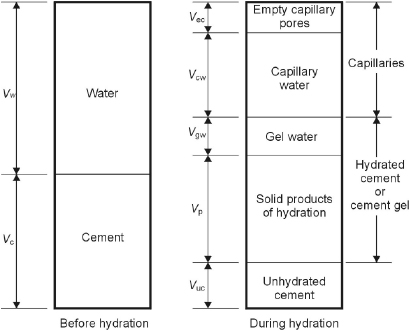
Figure 1.4 Example of microstructure of hydrated cement paste (scanning electron microscope).
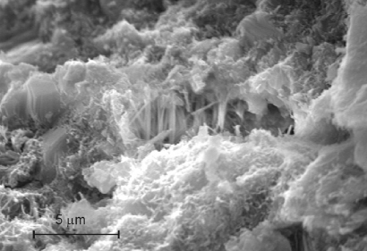
Figure 1.5 Influence of the water/cement ratio (a) and curing (b) on the distribution of pore size in hydrated cement pastes [3].
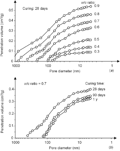
In conclusion, the volume of the capillary pores (Vcp = Vcw + Vec) in the cement paste increases with the amount of water used in the paste and thus with the water/cement ratio (w/c) and decreases with the degree of hydration (h), that is, the fraction of hydrated cement. The effect of w/c and h on the volume of capillary pores (Vcp in liters per kg of cement) can be described by the following formula, proposed by Powers [8]:
(1.3) 
When concrete is considered instead of cement paste, the w/c ratio and degree of hydration remain the main factors that determine the capillary porosity. Nevertheless, concrete is more complex because of the presence of the aggregates and the interfacial transition zone. The interfacial transition zone is a layer (usually several tens of micrometers thick) of hydrated cement paste in contact with aggregates. Especially for coarse aggregates, the hydrated cement paste in this area is typically heterogeneous and has a higher porosity compared to bulk cement paste [2–4].
In determining the resistance to degradation of concrete and its role in protecting the embedded steel, not only the total capillary porosity (i.e., the percentage of volume occupied by capillaries) should be considered, but also the size and interconnection of capillary pores. Figure 1.6 shows the relation between the transport properties of cement paste (expressed as coefficient of water permeability) and the compressive strength as a function of the w/c ratio and degree of hydration. The decrease in capillary porosity increases the mechanical strength of cement paste and reduces the permeability of the hydrated cement paste. A distinction should be made between capillary pores of larger dimensions (e.g., >50 nm), or macropores, and pores of smaller dimensions, or micropores [3]. The reduction in porosity resulting of both the macro- and the micropores plays an essential role in increasing mechanical strength.
Figure 1.6 Influence of capillary porosity on strength and permeability of cement paste (a). Capillary porosity derives from a combination of water/cement ratio and degree of hydration (b)
(Powers [7] from [3]).
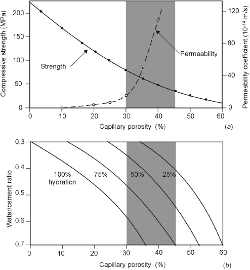
On the other hand, the influence of porosity on transport processes cannot be explained simply by the pore volume, the concept of connectivity or the degree of continuity of the pore system also has to be taken into account. At high porosities the interconnected capillary pore system (Figure 1.4) extends from the surface to the bulk of the cement paste. Permeability is high (Figure 1.6) and transport processes like for example, capillary suction of (chloride-containing) water can take place rapidly. With decreasing porosity the capillary pore system loses its connectivity, thus transport processes are controlled by the small gel pores. As a result, water and chlorides will penetrate only a short distance into cement paste. This influence of structure (geometry) on transport properties can be described with the percolation theory [9]: below a critical porosity, pc, the percolation threshold, the capillary pore system is not interconnected (only finite clusters are present); above pc the capillary pore system is continuous (infinite clusters). The percolation theory has been used to design numerical experiments and applied to transport processes in cement paste and mortars [10].
The steep increase of the water permeability above ca. 25% porosity (corresponding to a w/c ratio of 0.45 with a degree of hydration of 75%, Figure 1.6) is the background of the specified values in the codes of practice for high quality concrete. For instance, Table 1.2 shows the relationship between water/cement ratio and degree of hydration in order to achieve segmentation of the macropores in a paste of portland cement. This relationship was proposed by Powers for portland cement pastes in the 1950s.
Table 1.2 Curing times necessary to achieve a degree of hydration capable of segmenting the macropores in a portland cement paste (Powers from [2]).
| w/c | Degree of hydration | Curing |
|---|---|---|
| 0.40 | 50% | 3 days |
| 0.45 | 60% | 7 days |
| 0.50 | 70% | 14 days |
| 0.60 | 92% | 6 months |
| 0.70 | 100% | 1 year |
| >0.70 | 100% | Impossible |
The use of portland cement clinker is continuously decreasing, being replaced by supplementary cementitious materials (SCM). These new types of cements are obtained by intergrinding or blending portland cement with particular mineral substances.2) Among these types of binders, those with the addition of pozzolanic materials or ground granulated blast furnace slag are of particular interest with regard to durability of reinforced concrete.
Pozzolanic materials can be either natural, like pozzolana, or artificial, like fly ash and silica fume [4]. They are mainly glassy siliceous materials that may contain aluminous compounds but have a low lime (calcium hydroxide) content. In themselves they do not have binding properties, but acquire them in the presence of lime, giving rise to hydration products similar to those of portland cement.
The reaction between pozzolanic materials, lime and water is known as the pozzolanic reaction:
(1.4) 
In cements containing pozzolanic additions, the lime needed to react with pozzolana is provided by the hydration of portland cement. The hardened cement paste (compared to that obtained with ordinary portland cement) has a lower lime content and higher content of C–S–H. The amount of pozzolanic addition to portland cement should be adjusted to the amount of lime produced in the hydration of portland cement. Any excess of the pozzolanic addition will not react and thus will behave as an inert addition (“filler”).
This is a sedimentary material, usually of pyroclastic origin, that is derived from the sediment of volcanic eruptions that has produced incoherent deposits or compact deposits that have been chemically transformed with time (such as Italian pozzolana that was already used by the Romans). Pozzolanic materials may also have other origins, such as diatomaceous earth composed of the siliceous skeletons of micro-organisms. The pozzolanic activity of these materials is related to their siliceous component in the vitreous state and to their fineness [11]. There are also pozzolana that are obtained by calcination of natural substances.
Fly ash (also called pulverized fuel ash, PFA) is a byproduct of the combustion of coal powder in thermoelectric power plants [12]. It consists of fine and spherical particles (dimensions from 1 to 100 μm and specific surface area of 300 to 600 m2/kg) that are collected from exhaust gases with electrostatic or mechanical filters. Its composition depends on the type of coal it derives from; the most common PFA is mainly siliceous. Because it is formed at high temperature and subsequently undergoes rapid cooling, its structure is mainly amorphous and thus reactive. Fly ash is normally added in amounts between 15% and 30%; binders with higher amounts are termed “high-volume fly ash” materials.
Silica fume (SF) is a waste product of manufacturing ferro-silicon alloys. It consists of an extremely fine powder of amorphous silica. Average particle diameter is about 100 times smaller than that of portland cement and the specific surface area is enormous: 13 000–30 000 m2/kg compared to 300–400 m2/kg for common portland cements. Silica fume shows an elevated pozzolanic activity and is also a very effective filler [13]. For these reasons, addition of silica fume to portland cement may lead to a very low porosity of the cement paste, increasing the strength and lowering the permeability. It is usually added in the proportion of 5 to 10% and it is combined with the use of a superplasticizer in order to maintain adequate workability of the fresh concrete.
Production of pig iron generates great quantities of liquid slag, which is composed like portland cement of lime, silica, and alumina, although in different proportions. The slag acquires hydraulic properties if it is quenched and transformed into porous granules with an amorphous structure. This is then ground to obtain a powder whose fineness is comparable to that of cement, which is called ground granulated blast furnace slag (GGBS) [2].
Unlike pozzolanic materials, which hydrate only in the presence of lime, slag has latent hydraulic characteristics and thus might be used as a hydraulic binder. The rate of hydration of this process is, however, too slow for practical purposes. This material shows good hardening properties when mixed with portland cement, because the hydration of portland cement creates an alkaline environment that activates the reaction of GGBS. Nevertheless, even when activated by portland cement, the hydration of GGBS is slower than that of portland cement. To achieve a high early strength, the slag content should be relatively low (35–50%). The hydration of GGBS, however, refines the pore structure of the cement paste; in order to achieve an optimal densification of the cement paste the GGBS content should be higher than 65%.
Blast furnace slag cement with improved properties with regard to both early strength and density has been introduced. It is a CEM III/A 52.5 containing 57% finely ground slag and rapid hardening portland cement. It has a better resistance to carbonation than CEM III/B, and a similarly good resistance to chloride penetration and alkali-silica reactions. Its relatively high early strength makes it suitable for use in the precast concrete industry.
Besides additions with pozzolanic or hydraulic properties, ground limestone may also be used [14]. In Europe the use of portland cement blended with about 15–20% of ground limestone is continuously increasing, mainly due to saving of CO2 emissions, and in some countries this type of binder is by far the most widely used. Even though some reaction of fine carbonate particles with hydration products of portland cement may occur and replacement of small amounts (10–15% by mass) of portland cement with ground limestone may not significantly affect the strength of concrete (due to an accelerating effect on hydration of the C3S phase), this addition is essentially inert.
A large number of new additions have been considered in order to study possible advantages of their incorporation in blended cements. This is often justified by environmental issues [15]. Materials that show pozzolanic or hydraulic properties may replace the clinker of portland cement, reducing the consumption of energy and raw materials as well as the pollution associated to its production (e.g., total CO2 emissions for the production of clinker, coming both from the fuel and the decomposition of limestone, range from 0.84 to 1.15 kg per kg of clinker for kilns burning conventional fuels and raw materials [16]). Furthermore, most of the proposed materials, such as metakaolin, rice husk ash, recycled glass or even ashes from municipal solid waste incineration, are wastes, so they can be reused, avoiding their disposal [17].
Several mineral additions have also been shown to improve the resistance of concrete materials to the penetration of aggressive ions [18]. So the research in this field may produce interesting results also regarding the durability of reinforced concrete structures.
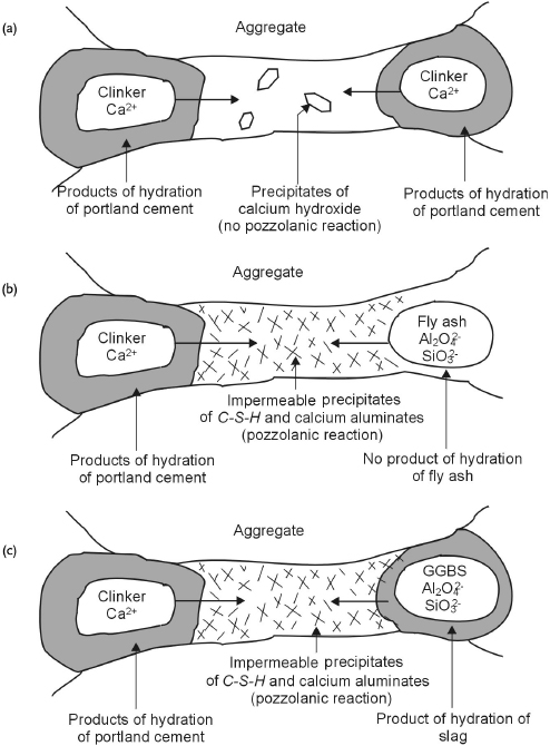
Cement paste obtained with blended cements differs considerably from that obtained with portland cement. The hydration of pozzolanic materials or GGBS consumes lime and thus reduces its amount with respect to a cement paste obtained with portland cement. Figure 1.7 outlines the microstructures of hardened cement pastes made of portland cement and blended cements [19]. It can be observed that the addition of PFA or GGBS leads to the formation of very fine products of hydration that lead to a refinement of pores. Consequently, an increase in the resistance to penetration of aggressive agents can be obtained. However, the reactions of pozzolanic materials or GGBS are slower than hydration of portland cement; hence this effect will be achieved only if the wet curing of the concrete is long enough.
Figure 1.7 Microstructure of hydration of portland cement (a), and cements with addition of fly ash (b) and blast furnace slag (c)
(Bakker from [19]).
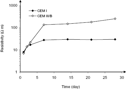
The rate of reaction of blast furnace slag and fly ash differs strongly. To show this, Figure 1.8 compares electrical resistivity measurements of wet cured concrete with a water/cement ratio of 0.45 made with portland, portland fly ash and blast furnace slag cements. The development of resistivity of concrete at an early age shows the changes that occur in the microstructure of cement paste (Section 2.5.3). From the age of one week on, the resistivity of blast furnace slag cement (CEM III/B) was more than three times higher than for portland (CEM I) and portland fly ash (CEM II/B-V) cement [20]. The resistivity of PFA concrete became significantly higher than that of ordinary portland cement concrete from about eight weeks of age. Recent work has shown that CEM III/B mortar shows lower resistivity than CEM I mortar up to a few days age [21]; from three days on, the situation is reversed, as is shown in Figure 1.9. It appears, then, that the refinement of the pore structure by GGBS starts as early as a few days, while the effect of PFA takes several weeks to months to develop. Silica fume is also known to react quickly.
Figure 1.8 Electrical resistivity of concrete made with different cements from 7 days age while exposed in a fog room (w/c = 0.45, 2% chloride mixed in) [20].

Figure 1.9 Electrical resistivity of mortar (w/c 0.50) made with portland and blast furnace slag cements at early age
(based on data from [21]).
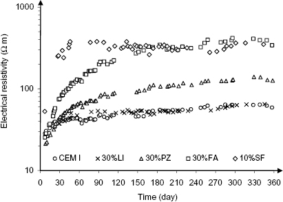
Regarding the addition of ground limestone, it was observed that the electrical resistivity measured on saturated mortar specimens made with limestone cement was similar to that measured on specimens made with portland cement, as is shown in Figure 1.10, which highlights the fact that unlike pozzolanic additions ground limestone does not improve the impermeability of hydrated cement paste [22].
Figure 1.10 Electrical resistivity of water-saturated mortars with different additions as a function of time after casting (w/b = 0.5): CEM I = portland cement, 30%LI = 30% ground limestone, 30%PZ = 30% natural pozzolana, 30%FA = 30% coal fly ash, 10%SF = 10% silica fume
(modified from [22]).
According to the European standard EN 197-1 [23], cements can be classified on the basis of composition and standard strength at 28 days.
As far as composition is concerned, five main types of cement can be considered:
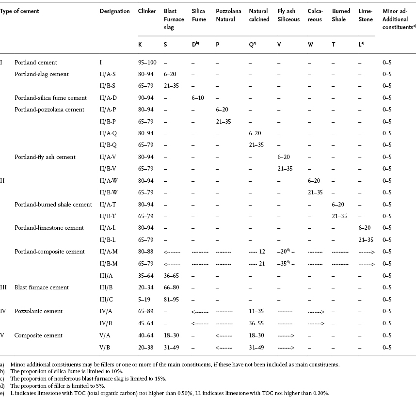
Table 1.3 shows the composition and the designation of the types of cement provided by EN 197-1. For CEM II and CEM V, additions of substances that do not contribute to hydration, such as limestone, is also allowed. In each type of cement, minor additional constituents (such as fillers3)) may be added up to 5% by mass.
Table 1.3 Types of cement according to EN 197-1 and their composition (% by mass; values in the table refer to the nucleus of cement, excluding calcium sulfate) [23].
To evaluate the performance of a cement at 28 days of moist curing, that is, when the strength of concrete is normally tested, the standard strength classes have been introduced. These are conventionally defined on the basis of the characteristic compressive strength measured on standardized mortar prisms with a w/c ratio equal to 0.5 and a sand/cement ratio of 3, cured for 28 days in moist conditions. For each type of cement, three classes of 28-day strength are potentially available; furthermore, depending on early strength each class is then divided into normal (N), high early strength (R) or low early strength (L, only applicable for CEM III cements), as shown in Table 1.4. The strength classes are essentially a measure of the rate of hydration of the cement: the higher the strength at a given time, the higher the rate of hydration.
Table 1.4 Strength classes of cement according to EN 197-1 [23].

Designation of cement indicates the cement type (Table 1.3) and the strength class (Table 1.4). For instance, CEM II/A-S 42.5N indicates portland-slag cement with addition of blast furnace slag in the range of 6–20% and strength class 42.5 with normal early strength.
EN 197-1 also provides other requirements of cement such as setting times and chemical properties. Methods of testing these properties are described in the European standards of the series EN 196.
Other types of cement than those listed in Table 1.3 are available for special uses. These are for instance: low heat cements to be used when low heat of hydration is desired such as in massive structures, sulfate-resisting cements to be used to increase the resistance of concrete to sulfate attack, expansive cements, quick setting cements, white or colored cements, etc. [2, 4]. New types of cement are under study in order to reduce the environmental impact and improve sustainability; care should be used in the selection of new types of cements, since the long-term durability performance is unknown.
Mention should be made of high alumina cement (HAC). In fact, although nowadays it is generally not used for structural purposes, in the past its use has caused problems of durability (as well as from the structural point of view), especially in countries like Spain and the United Kingdom where it was extensively used. It is obtained by melting a suitable mixture of limestone and bauxite (mainly consisting of alumina) at about 1600 °C. Its primary constituent is CaO·Al2O3 (CA). The hydration reaction (CA + 10H = CAH10) mainly produces CAH10, which is unstable. In humid environments whose temperature exceeds 25 °C a process of conversion takes place: hydration products transform into another compound (C3AH6). This transformation induces a considerable increase in porosity, and thus a drastic loss of strength and a decrease in the resistance to aggressive agents, especially to carbonation. The degree to which the porosity will increase and related consequences occur, depends on the w/c ratio used, and is much greater when this ratio exceeds 0.4.
In some countries, HAC has more recently been used to obtain acid-resistant (sewage) pipe or lining. During production, the w/c is kept below 0.4 and thermal treatment is applied during the manufacturing process, deliberately forcing the conversion to the stable compound (C3AH6). If the strength and density of the converted material are adequate, the durability is good. The stable product has a high resistance against attack by acids. HAC concrete also has good properties for high-temperature applications (e.g., furnaces).
The use of raw materials such as limestone, bauxite, and calcium sulfate leads to 20–30% reduced CO2 emission compared to equivalent ordinary portland cement and to a lower firing temperature of 1250 °C. Further, calcium sulfoaluminate (CSA) cement is easier to grind than portland cement clinker. The setting time of CSA is between 30 min and 4 h, most of the hydration heat evolution occurs between 2 and 24 h of hydration. Due to a denser pore structure concrete with CSA cements has a high resistance to freeze–thaw and against chemical attack by seawater, sulfates and magnesium and ammonium salts. However, the durability of reinforced concrete with CSA cement has to be considered lower: the pH of the pore solution is one unit lower compared to ordinary portland cement and the carbonation rate has been found to be higher [24].
Notes
1) In the chemistry of cement, the following abbreviations are used: CaO = C; SiO2 = S; Al2O3 = A; Fe2O3 = F; H2O = H;  .
.
2) In the presence of blended cements the definition of the w/c ratio may be ambiguous and deserves some attention. Usually the mass of cement refers to the blended cement, and so it includes the addition. Unless otherwise indicated, this will be done in this book. It should be noted that the effect of w/c on durability related parameters is strictly related to the composition of the binder. So, the requirement for w/c should always be associated to a specific type of cement. If the addition is not interground with cement, but it is added at the concrete plant, the mass of cement in the w/c ratio will normally not include it and the concept of water/binder ratio (w/b) is introduced. Water/binder ratio will also be used as a general term when distinction between addition at the cement plant or at the concrete plant is not relevant.
3) Fillers are finely ground natural or artificial inorganic materials, which may be added to improve the physical properties of cement such as its workability, or to achieve requirements of mechanical strength.