Table of Contents
Introduction
Chapter 1 History, Present and Future of WPT
1.1. Theoretical predictions and the first trial in the 19th Century
1.2. Rejuvenated WPT by microwaves in the 1960s
1.3. Inductive coupling WPT projects in the 20th Century
1.4. WPT as a game-changing technology in the 21st Centur
Chapter 2 Theory of WPT
2.1 Theoretical background
2.2. Beam efficiency and coupling efficiency
2.3. Beam forming
2.4. Beam receiving
Chapter 3 Technologies of WPT
3.1. Introduction
3.2. Radio frequency (RF) generation – HPA using semiconductors
3.3. RF generation – microwave tubes
3.4 Beam-forming and target-detecting technologies with phased array
3.5. RF rectifier – rectenna and tube type
Chapter 4 Applications of WPT
4.1. Introduction
4.2. Energy harvesting
4.3. Sensor network
4.4. Ubiquitous power source
4.5. MPT in a pipe
4.6. Microwave buildings
4.7. 2D WPT
4.8. Wireless charging for electric vehicles
4.9. Point-to-point WPT
4.10. WPT to moving/flying target
4.11. Solar power satellite
Bibliography
Index
First published 2014 in Great Britain and the United States by ISTE Ltd and John Wiley & Sons, Inc.
Apart from any fair dealing for the purposes of research or private study, or criticism or review, as permitted under the Copyright, Designs and Patents Act 1988, this publication may only be reproduced, stored or transmitted, in any form or by any means, with the prior permission in writing of the publishers, or in the case of reprographic reproduction in accordance with the terms and licenses issued by the CLA. Enquiries concerning reproduction outside these terms should be sent to the publishers at the undermentioned address:
ISTE Ltd
27-37 St George’s Road
London SW19 4EU
UK
www.iste.co.uk
John Wiley & Sons, Inc.
111 River Street
Hoboken, NJ 07030
USA
www.wiley.com
© ISTE Ltd 2014
The rights of Naoki Shinohara to be identified as the author of this work have been asserted by him in accordance with the Copyright, Designs and Patents Act 1988.
Library of Congress Control Number: 2013952542
British Library Cataloguing-in-Publication Data
A CIP record for this book is available from the British Library
ISBN 978-1-84821-605-1

Introduction
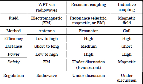
Wireless power transfer (WPT) is a promising technology based on electromagnetic theory and radiowave theory, representing the combined application of electrical and radio sciences. There are numerous WPT technologies, such as inductive coupling WPT (Figure I.1(a)) and resonant coupling WPT (Figure I.1(b)) as short distance WPT. In addition, WPT via radiowaves has been developed as a long-distance WPT technology, which includes focused beam microwave power transfer (MPT) (Figure I.1(c)) and energy harvesting from broadcasted radiowaves or diffused wireless power (Figure I.1(d)). Both inductive coupling WPT and resonant coupling WPT are based on electromagnetic theory. A transmitter and a receiver are electromagnetically coupled and power is wirelessly transmitted via an electric field, a magnetic field, or an electromagnetic field. Unlike the short-range technologies, WPT via radiowaves does not require coupling between the transmitter and the receiver, but it uses radiated electromagnetic waves. WPT via radiowaves requires higher frequencies, such as microwaves, to focus on the wireless power effectively. The general characteristics of various WPT technologies are described in Table I.1. The primary difference between inductive and resonant coupling is the presence of non-resonance and resonance, respectively. In the case of short distances, inductive or resonant coupling technologies using coils are effective, but the coupling distance is limited by coupling theory even for resonant coupling. To expand the distance over which power can be transferred, radiowaves are necessary to carry the energy. For WPT via radiowaves, antennas are used for power radiation and receiving. The antenna serves as a resonator to radiate radiowaves effectively.
Figure I.1. Various WPT technologies: a) inductive coupling, b) resonant coupling, c) WPT via focused beam radiowaves and d) energy harvesting via diffused radiowaves
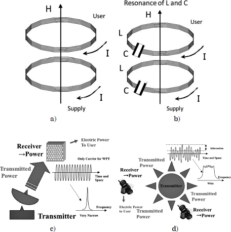
Table I.1. Characteristics of WPT technologies
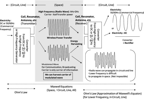
All WPT technologies are based on Maxwell’s equations. However, there are minor differences in their applications. It is now possible to use higher frequency radiowaves, for example in the gigahertz (GHz) range of microwaves, to focus on electric power wirelessly at sufficient levels and on beam efficiency to satisfy the needs of many applications. A WPT system is shown in Figure I.2. Frequency converters are used to transform electricity into wireless power, and vice versa. The primary difference between electricity and wireless power is only a matter of the frequency. It is also possible to transmit wireless power from multitransmitting antennas to multireceiving antennas like broadcasting and wireless communications because the antennas are not coupled electromagnetically. Very low power WPT systems do not even require battery storage and can be run on the energy harvested from ambient radio frequency (RF) and microwave radiation. Additionally, the extent of battery storage can be reduced when wireless power is widespread because batteries can be charged wirelessly and, hence, shortages of battery storage are not a concern.
Figure I.2. A WPT system
This scenario will soon be a reality. WPT via radiowaves is, in fact, a valuable and convenient technology that can be used to charge batteries in mobile phones, notebook personal computers (PCs), electric vehicles (EVs), as well as battery storage for light emitting diodes (LEDs), integrated circuits (ICs) and other equipment. In the near future, stable CO2-free electric power from space will be possible using WPT technology. The concept of a space-based solar power satellite (SPS) is supported by MPT. The SPS is a gigantic power station built in space. The SPS is a primary system of significance to the concept of the “humanosphere”. The humanosphere concept corresponds to the description of Earth as a space where human activity takes place. Humanospheric science is defined as an interdisciplinary science that conducts research concerning the humanosphere. This science is a significant development for the future of the human race. A pictographic description of the humanosphere and humanospheric science is shown in Figure I.3. To maintain human welfare and the current standard of living, or even to avoid disaster during this century, the issues of energy, food and the environment should be seriously addressed. Presently, the increasing demand for electricity conflicts with the demand for a clean environment due to the use of fossil-based power production. Electricity has heretofore been generated through various methods, such as hydroelectric power, fossil thermal power and atomic power. However, some of these methods are causes of environmental and pollution issues all over the world. Under these circumstances, research has been carried out to investigate the possibility of building power stations in space to transmit electricity, generated in space, to the Earth via radiowaves. It is believed that WPT technologies support this vision of a bright future.
Figure I.3. A pictographic description of the “humanosphere” and humanospheric science

In 1864, James C. Maxwell predicted the existence of radiowaves by means of a mathematical model. The so-called Maxwell equations are the most famous and most successful formulas. In 1884, John H. Poynting realized that the Poynting vector would play an important role in quantifying electromagnetic energy. In 1888, bolstered by Maxwell’s theory, Heinrich Hertz first succeeded in showing experimental evidence of radiowaves using his spark-gap radio transmitter. The prediction and evidence of radiowaves toward the end of the 19th Century was the beginning of wireless power transfer (WPT).
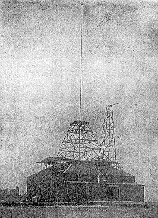
During the same period, when Marchese G. Marconi and Reginald Fessenden pioneered communication via radiowaves, Nicola Tesla suggested the idea of wireless power transfer and carried out the first WPT experiments in 1899 [TES 04a, TES 04b]. He said “This energy will be collected all over the globe preferably in small amounts, ranging from a fraction of one to a few horse-power. One of its chief uses will be the illumination of isolated homes”. Tesla actually built a gigantic coil that was connected to a 200 ft high mast with a 3 ft diameter ball at its top. The device was called the “Tesla Tower” (Figure 1.1). Tesla fed 300 kw of power to the coil that resonated at a frequency of 150 kHz. The radio frequency (RF) potential at the top sphere reached 100 MV. Unfortunately, the experiment failed because the transmitted power was diffused in all directions using 150 kHz radiowaves, whose wavelength was 21 km. After this first WPT trial, the history of radiowaves has been dominated by wireless communications and remote sensing.
Figure 1.1. The Tesla tower
To focus on the transmitted power and to increase the transfer efficiency, a higher frequency than that used by Tesla is required. In the 1930s, a great deal of progress in generating high-power microwaves in the 1–10 GHz range was achieved by the invention of the magnetron and the klystron. After World War II, high-power and high-efficiency microwave tubes were advanced by the development of radar technology. The power delivered to a receiver can be concentrated with microwaves. WPT using microwaves is called microwave power transfer (MPT).
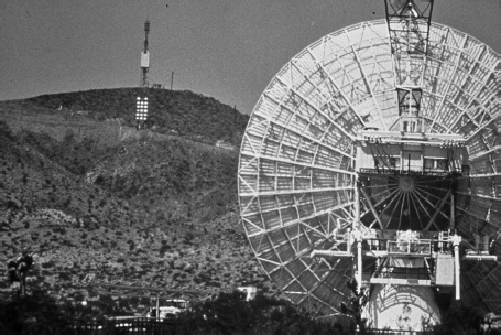
On the basis of development of microwave tubes during World War II, W.C. Brown introduced the first MPT research and development in the 1960s. First, Brown developed a rectifying antenna, which he named a “rectenna” for receiving and rectifying microwaves. The efficiency of the first rectenna developed in 1963 was 50% at an output of 4 WDC and 40% at an output of 7 WDC, respectively [BRO 84]. With the rectenna, Brown successfully applied MPT to a wired helicopter in 1964 and to a free-flying helicopter in 1968 (Figure 1.2). In the 1970s, Brown attempted to increase the total DC–RF–transfer–RF–DC efficiency using 2.45 GHz microwaves. The overall DC–DC efficiency was only 26.5% at an output of 39 WDC in the Marshall Space Flight Center tests of 1970 [BRO 73a]. In 1975, the overall DC–DC efficiency finally attained 54% at an output of 495 WDC using the Raytheon Laboratory magnetron (Figure 1.3) [BRO 84]. In parallel, Brown, Richard Dickinson and his team succeeded in the largest MPT demonstration up to that time in 1975 at the Venus Site of the JPL Goldstone Facility (Figure 1.4). The distance between the transmitting parabolic antenna, whose diameter was 26 m, and a rectenna array, whose size was 3.4 m × 7.2 m, was 1 mile. The transmitted 2.388 GHz microwave signal was 450 kW from the klystron and the rectified DC power achieved was 30 kW DC with a 82.5% rectifying efficiency. On the basis of Brown’s work, P.E. Glaser proposed a solar power satellite (SPS) system in 1968 [GLA 68].
Figure 1.2. MPT Helicopter demonstration by W.C. Brown in 1964 [BRO 84]
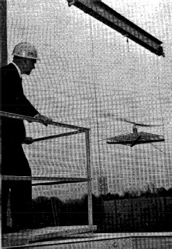
Figure 1.3. MPT laboratory experiment by W.C. Brown in 1975 [BRO 84]
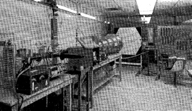
Figure 1.4. First ground-to-ground MPT experiment in 1975 at the Venus Site of the JPL Goldstone Facility
But after the MPT experiments of the 1960s, SPS applications have led the field in MPT research [MCS 02, MAT 02a]. Because of the theoretical calculation, the large antenna size required to achieve high-beam efficiency to a far distant target, an MPT system designed for SPS did not seem to be suitable for commercial applications. However, even if the antenna size was to become larger, there would be the other merits of the space-based SPS. The SPS is designed as a huge SPS in geostationary orbit, 36,000 km above the Earth’s surface, where there is no cloud cover and no night throughout the year. Microwave energy is not absorbed by air, cloud and rain; therefore, it is possible to obtain approximately 10 times the solar power, a stable and CO2-free energy source, from the SPS using MPT technology than that from terrestrial solar sources. As a result of the high benefits expected, MPT research mainly focused on SPS applications during the late 20th Century.
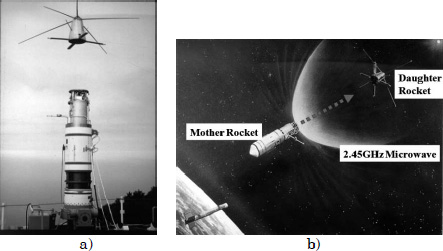
Numerous Japanese scientists developed MPT technologies and research throughout the 1980s [MAT 95a, MAT 02a]. In 1983 and 1993, Hiroshi Matsumoto’s team carried out the first MPT experiment in space. The rocket experiment in 1983 was called the microwave ionosphere nonlinear interaction experiment (MINIX) (Figure 1.5), and International Space Year – Microwave Energy Transmission in Space (ISY-METS) was conducted in 1993. These experiments focused on the nonlinear interaction between intense microwaves and ionospheric plasmas. In the MINIX experiment, the researchers used a cooker-type 800 W, 2.45 GHz magnetron for a microwave transmitter. New wave–particle interaction phenomena were observed during the MINIX study. Plasma theory and computer experiments supported the observations [MAT 95b, MAT 95c]. These rocket experiments were directed toward SPS applications.
Figure 1.5. The first rocket experiment by Matsumoto in Japan in 1983, called the MINIX project: a) image of mother and daughter rockets; b) image of the experiment
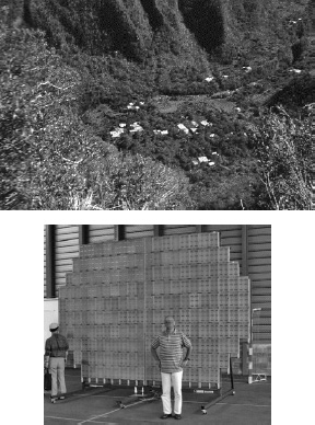
During the 1990s, numerous MPT laboratory and field experiments were carried out all over the world. This research was not only for SPS but also for other commercial MPT applications. Researchers often used 2.45 or 5.8 GHz frequencies of the industry, science and medical (ISM) band for MPT systems. A Canadian group of the Communication Research Centre (CRC) successfully conducted a fuel-free airplane flight experiment using MPT in 1987, which was called stationary high-altitude relay platform (SHARP) (Figure 1.6) [SCH 88, SHA 88]. They transmitted a 2.45 GHz, 10 kW microwave signal to a model airplane, having a total length of 2.9 m and a wing span of 4.5 m, flying more than 150 m above ground level. In the United States, a great deal of MPT research and development continued after Brown. For instance, retrodirective microwave transmitters, rectennas, new devices and microwave circuit technologies were investigated [BRO 88]. In Japan, several field MPT experiments were conducted, such as fuel-free airplane flight experiments with MPT phased arrays operating at 2.411 GHz for the microwave lifted airplane experiment (MILAX) project in 1992 (Figure 1.7) [MAT 93], ground-to-ground MPT experiments operating at 2.45 GHz were conducted by power companies and universities in 1994–1995 (Figure 1.8) [SHI 98a], and fuel-free light airship experiments using MPT operating at 2.45 GHz in 1995 [KAY 96]. The target system used in the MILAX project was the Japanese SHARP. Kobe University and Communications Research Laboratory (CRL; present National Institute of Information and Communications Technology (NICT)) group in Japan succeeded in an MPT field experiment involving a flying airship in 1995. They called it the Energy Transmission toward High-altitude long endurance airship Experiment (ETHER) project. This research group transmitted 2.45 GHz, 10 kW microwaves to a flying airship 35–45 m above ground level. In these experiments, except in those of the MILAX project, researchers adopted a parabolic antenna MPT system using a microwave tube. A phased array system was used only in the MILAX project, and this project was the first MPT field experiment to use it. In parallel with developments in Japan, varieties of microwave transmitters, retrodirective microwave transmitters and, especially, rectennas were also developed. In Europe, some unique technologies are presently being developed. Researchers had planned ground-to-ground MPT experiments on Réunion Island (Figure 1.9) [CEL 97, CEL 04], but the project has not yet been carried out.
Figure 1.6. The Canadian SHARP flight experiment and the 1/8 model airplane in 1987 [SHA 88]
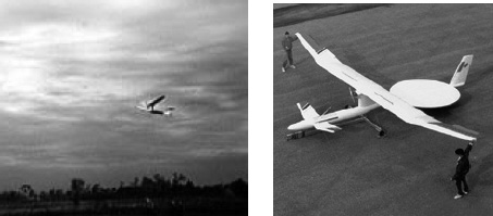
Figure 1.7. The MILAX project airplane experiment showing the model airplane and the phased array used in Japan in 1992
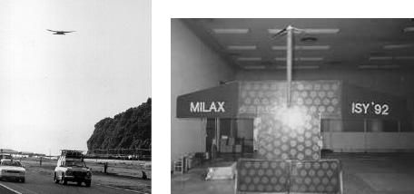
Figure 1.8. Ground-to-ground MPT experiment in Japan in 1994–1995
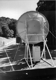
Figure 1.9. Grand bassin, Réunion, France and their prototype rectenna [CEL 04]
Maxwell integrated Ampere’s law and Faraday’s law into his equations. Prior to Maxwell’s equations, it was known from Ampere’s Law and Faraday’s Law that a current creates a magnetic field and a changing magnetic field recreates a current. Two conductors are referred to as mutual-inductively coupled or magnetically coupled when they are configured such that a change in the current flow through one conductor induces a voltage across the ends of the other via electromagnetic induction. The phenomenon is called inductive coupling and is applied for power generators and transformers. Contrary to WPT via radiowaves, lower frequencies in the kilohertz to megahertz range are typically used for inductive coupling WPT.
Parallel to Tesla’s first WPT experiments, M. Hutin and M. Le-Blanc proposed an apparatus and method for powering an electrical vehicle (EV) inductively in 1894 using an approximately 3 kHz AC generator [HUT 94]. EVs were developed shortly after the development of the steam engine, approximately 100 years ago. However, the EV became less popular with development of the internal combustion engine. As a result, after Hutin and Le-Blanc, the EV inductive coupling WPT charger was forgotten like Tesla’s dream of WPT.
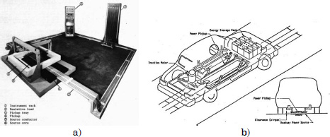
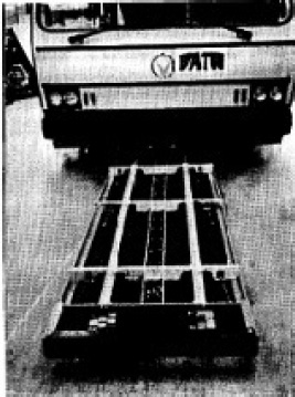
Professor Don Otto of the University of Auckland in New Zealand proposed an inductively powered vehicle in 1972 using the power generated at 10 kHz, by a force commutated sinusoidal silicon controlled rectifier inverter [OTT 74]. He adopted two circular cross-section conductors of copper, one of which was placed on the road as a transmitter and the other was placed on the body of the EV at a position 20 cm above the road surface. In 1978, the USA group of J.G. Bolger, F.A. Kirsten and S. Ng carried out the first EV-WPT application in the United States. They used a 180 Hz and 20 kW WPT system whose size was 60 cm × 1.52 m and its air gap was 2.5 cm (Figure 1.10). In the 1980s, another WPT project was conducted in California, USA. It was called the Partner for Advanced Transit and Highways (PATH) project (Figure 1.11) [BOL 78, ZEL 82]. The work achieved a 60% efficiency powering a bus using machine-generated electric power at 400 Hz coupled across an air gap to drive the bus at a distance of 50–100 m [SYS 94]. Researchers in France and Germany conducted EV-WPT projects in the 1980s–1990s known as TULIP (Transport Urban, Individuel et Public – Public and Individual Urban Transport) and Inductive Power Transfer (IPT), respectively.
Figure 1.10. a) Experimental setup of the first U.S. EV-WPT experiment; b) image of the experiment
Inductive coupling is not only used for EV-WPT research projects but also for commercial, non-attached power supply of an electric kettle, an electric shaver, an electric toothbrush, etc. The integrated circuit (IC) card is one of the most famous applications of inductive coupling. In 1995, Sony proposed and developed the Felica system in Japan that used the IC card and adopted an inductive coupling wireless power supply with a 13.56 MHz signal. These inductive coupling WPT applications are used globally. However, there has yet to be any global standard developed for WPT technology and WPT systems vary considerably.
Figure 1.11. Experimental setup of the PATH project in the U.S. in the 1980s
The other recent trend in WPT began with the use of resonant coupling in the United States by the Massachusetts Institute of Technology (MIT) [KUR 07] in 2006. The resonant coupler is well known as a microwave band-pass filter (BPF). The team at MIT applied the BPF to wireless power transfer. With this technique, a large amount of power (from watts to kilowatts) can be transmitted without radiation over mid-length distances (more than a few meters) at low frequencies (less than 10 MHz) using simple resonant circuits. It became evident that resonant coupling WPT is more suitable for commercial needs. Resonant coupling is based on the inductive coupling of magnetic fields. As shown in section 1.3, various research projects and products using inductive coupling WPT technology have been pursued prior to MIT’s revolution. This research and resulting products have supported both theory and development of resonant coupling WPT technology.
The Wireless Power Consortium (WPC) was established in December 2008 to develop wireless charging of mobile phones. They established the “Qi” standard for inductive coupling WPT in December 2010. Although there were some wireless charger developments for mobile phones with inductive coupling WPT, the work did not bear any commercially successful products. The “Qi” standard spread quickly in the world and wireless chargers using this standard have been able to be purchased of late. In addition to the WPC, various alliances, consortiums and forums for establishing a WPT standard and for promoting commercial applications have arisen as follows:
(Data as of September 2013)
The initial targets of the above forums and alliances are wireless charging of mobile phones and/or in-house applications of WPT. These groups aim to establish a global standard for commercial WPT and to expand commercial WPT applications in the world.
Resonant coupling WPT not only represents a coil system in a magnetic field but also an electrostatic induction coupling system with coupled conductors. In Japan, a wireless charger using resonant electrostatic induction coupling WPT technology has been commercialized for tablet charging. Additional research in Japan has been directed toward resonant electrostatic induction coupling WPT, which will be applied to free positioning electrical points [HAR 11]. This application uses 600 kHz, 1.2 MHz and 2.0 MHz signals selectively and has succeeded in 150 W of wireless power transfer with over 95% efficiency.
Many other high-power WPT activities exist. As an example, inductive coupling WPT has been applied to wireless charging of an electric bus by Hino Motors Ltd. [HIN 13] and Showa Aircraft Industry [SHO 13] in Japan. This so-called “inductive power transfer” was demonstrated and an inductive power transfer hybrid system was operated from April 13 to 27, 2009 (Figure 1.12).
There have been some studies on the application of resonant coupling WPT for electric vehicles [IMU 09, IMU 10]. Toyohashi University of Technology in Japan proposed a new concept of power transfer through a capacitor composed of a steel belt attached to the inside of a tire and a metal plate attached to the road (Figure 1.13) [HAN 11]. In 2011, Toyota Motor Co. invested in WiTricity Co., which is one of the first commercial developers of resonant coupling for wireless power transmission. IHI Co. was given a license from WiTricity Co. in 2011. Several other Japanese EV-WPT activities are described elsewhere [SHI 13a].
Figure 1.12. Field experimental setup for EV-WPT conducted in Japan in 2009
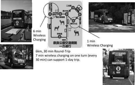
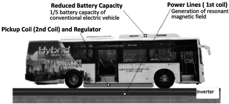
In Korea, a wireless power supply using a resonant coupling technique has been applied to an online electric vehicle (OLEV) (Figure 1.14) [AHN 11]. Power from the 60 Hz supply is converted to a frequency of 20 kHz by an inverter stage. A total of 60 kW of power may be transferred wirelessly from power lines with 80% efficiency.
Figure 1.13. a) Diagram of the power transfer system proposed by Toyohashi University of Technology, Japan [HAN 11]; b) experimental setup
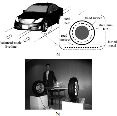
Figure 1.14. Wireless power supply for an online electric vehicle (OLEV) in Korea [AHN 11]
In the early 21st Century, G. Covic’s group in New Zealand continued to develop EV-WPT systems with inductive coupling. The group conducted research on a system composed of a multiphase track with multicoil receivers in 2003–2005, and IPT road pads with multicoil receivers in 2009–2010 [COV 12]. The German company Bombardier developed 250 kW WPT railways until 2012 [MEI 12]. Bombardier, BS-Verkehrs-AG, BS-energy and TU-Braunschweig began an EV-WPT project called Elecrobus in Branschweig in May 2012 [MEI 12]. It is a field EV-WPT experiment in downtown Branschweig.
In addition to these EV-WPT research activities, some companies, for example Evatran Co., Audi Co., SEW-EURODRIVE Co. and UniServices Co., introduced inductive coupling wireless power transmission systems for EV applications as commercial products. HaloIPT/Qualcomm Co. adopted resonant coupling WPT and began field experiments in London in 2012. Evatran Co. introduced a plugless level 2 EV Charging System using inductive coupling technology as a commercial product in 2013 [PLU 13]. To date, various WPT systems for robots and vehicles based on inductive coupling WPT technology have been installed in factories all over the world.
Contrary to inductive coupling and resonance coupling WPT, MPT applications seem to have been delayed because of radiowave regulation problems. Inductive coupling and resonance coupling produce less radiation as compared to MPT systems. However, MPT research groups have proposed advanced MPT systems as being acceptable for commercial use.