
Contents
About the companion website
Contributor list
Preface
List of videos
PART I Aorta
CHAPTER 1 Access techniques
Brachial access techniques used for aortic endografting
Techniques for constructing an endoconduit for aortic endografting
Transfemoral access techniques in aortic endografting
Retroperitoneal access for aortic endografting
CHAPTER 2 Equipment required for aortic endografting
Equipment lists
Further equipment information
CHAPTER 3 Advanced computed tomography imaging, workstations, and planning tools
CHAPTER 4 Technique of thoracic endografting for thoracic aneurysm using the approved Gore TAG device
Appendix: preference card
CHAPTER 5 Axillary/subclavian access for endovascular management of ascending and descending aortic pathologies
Introduction
Vascular access evaluation
Videoclips
CHAPTER 6 Endovascular repair of thoraco-abdominal aortic aneurysms
Endovascular alternatives for thoraco-abdominal aortic aneurysm repair
Principles of stent-graft design
Basic insertion technique
Patient selection
Preoperative preparation
Evolution of the device
Lessons of experience
Conclusions
CHAPTER 7 Hybrid endovascular aortic arch surgery
Introduction
Hybrid endovascular surgery
Personnel requirements
Imaging requirements
Access and device sizing
Landing zone optimization
Hybrid procedures
Anesthetic considerations
Procedural techniques
Cases
Outcomes
Complications
On the horizon
Conclusions
CHAPTER 8 Acute aortic dissection
Introduction
Epidemiology
Pathogenesis
Clinical findings
Diagnostic tests and imaging studies
Treatment
Conclusions
Acknowledgments
CHAPTER 9 Complications of endovascular aneurysm repair
Introduction
Complications
Conclusions
CHAPTER 10 Complications of thoracic aortic endografting
Introduction
Postoperative image surveillance for endoleaks
Type I endoleak
Type II endoleaks
Type III endoleaks
Complications
CHAPTER 11 Endovascular robotics for complex aortic intervention
Introduction
Advanced catheter technology
Robotic assistance for fenestrated stent-grafting
Future applications
Conclusions
Videoclip
PART II Structural heart disease
CHAPTER 12 Cardiovascular hybrid operating rooms
Introduction
Use of a hybrid operating room
Basics of the hybrid room
Imaging equipment
Imaging methods and technologies
Future trends in hybrid operating rooms
Conclusions
Videoclips
CHAPTER 13 Access techniques for transcatheter aortic valves
Introduction
Patient selection
Transcatheter aortic valve devices
Femoral access techniques
Retroperitoneal access techniques
Deployment of an endoconduit in small calcified and tortuous iliac vessel
Ventricular apical access techniques
Axillary artery access techniques
Carotid artery access techniques
Brachial artery access techniques
Conclusions
CHAPTER 14 Transfemoral transcatheter aortic valve replacement
Introduction
Patient selection
Approved device description
Transfemoral TAVR: procedural steps
TAVR-related complications
Clinical trial outcomes
Specific patient subgroups
Future transcatheter aortic valve platforms
Conclusions
Conflict of interest statement
CHAPTER 15 Transapical valve technology for aortic stenosis
Introduction
Aortic stenosis
Devices available for TAVR
Patient selection
Procedure details
Imaging requirements
Complications
Future evolution of TAVR and new devices
Videoclips
CHAPTER 16 Axillary/subclavian access for transcather aortic valve replacement
Introduction
General considerations
Patient selection and imaging
Surgical access
Advantages of the use of the axillary/subclavian access
Conclusions
CHAPTER 17 Aortic valve replacement and transvalvular aortic valve replacement
Introduction
Development of prostheses
Results
Discussion
Safety concerns
Conclusions
Videoclip
CHAPTER 18 Transcatheter mitral leaflet repair
Introduction
Edge-to-edge procedure
Transapical beating heart chordal replacement
Videoclips
CHAPTER 19 Mitral valve: valvuloplasty for mitral stenosis/mitral regurgitation and available devices
Anatomic aspects of the mitral valve
Imaging of the mitral valve
Valvuloplasty for mitral stenosis
Mitral regurgitation and available devices
MitraClip procedure
Conclusions
CHAPTER 20 Real-time magnetic resonance imaging guidance in cardiac surgery
Introduction
Interactive real-time magnetic resonance imaging
Magnetic resonance compatibility of the instruments and devices
Device tracking
MRI-guided transapical aortic valve replacement
Conclusions
Videoclip
CHAPTER 21 Patent ductus arteriosus
Introduction
Patent ductus arteriosus anatomy
Patent ductus arteriosus detection
Patient evaluation
Closure devices and procedural information
Challenging anatomy
Complications
CHAPTER 22 Patent foramen ovale
Introduction
Patent foramen ovale anatomy
Patent foramen ovale detection
Patient evaluation
Devices and procedural information
Challenging anatomy
Complications
CHAPTER 23 Articulated Robotic MedProbe snake robot for single port surgery
Introduction
ARM snake robot
Cardiorobotics, Inc.
First human use of the ARM snake robot
Future of the ARM snake robot: the next generation catheter
Index

This edition first published 2013 © 2013 by John Wiley & Sons, Ltd
Wiley-Blackwell is an imprint of John Wiley & Sons, formed by the merger of Wiley’s global Scientific, Technical and Medical business with Blackwell Publishing.
Registered Office
John Wiley & Sons, Ltd, The Atrium, Southern Gate, Chichester, West Sussex, PO19 8SQ, UK
Editorial Offices
9600 Garsington Road, Oxford, OX4 2DQ, UK
The Atrium, Southern Gate, Chichester, West Sussex, PO19 8SQ, UK
111 River Street, Hoboken, NJ 07030-5774, USA
For details of our global editorial offices, for customer services and for information about how to apply for permission to reuse the copyright material in this book please see our website at www.wiley.com/wiley-blackwell
The right of the author to be identified as the author of this work has been asserted in accordance with the UK Copyright, Designs and Patents Act 1988.
All rights reserved. No part of this publication may be reproduced, stored in a retrieval system, or transmitted, in any form or by any means, electronic, mechanical, photocopying, recording or otherwise, except as permitted by the UK Copyright, Designs and Patents Act 1988, without the prior permission of the publisher.
Designations used by companies to distinguish their products are often claimed as trademarks. All brand names and product names used in this book are trade names, service marks, trademarks or registered trademarks of their respective owners. The publisher is not associated with any product or vendor mentioned in this book. This publication is designed to provide accurate and authoritative information in regard to the subject matter covered. It is sold on the understanding that the publisher is not engaged in rendering professional services. If professional advice or other expert assistance is required, the services of a competent professional should be sought.
The contents of this work are intended to further general scientific research, understanding, and discussion only and are not intended and should not be relied upon as recommending or promoting a specific method, diagnosis, or treatment by physicians for any particular patient. The publisher and the author make no representations or warranties with respect to the accuracy or completeness of the contents of this work and specifically disclaim all warranties, including without limitation any implied warranties of fitness for a particular purpose. In view of ongoing research, equipment modifications, changes in governmental regulations, and the constant flow of information relating to the use of medicines, equipment, and devices, the reader is urged to review and evaluate the information provided in the package insert or instructions for each medicine, equipment, or device for, among other things, any changes in the instructions or indication of usage and for added warnings and precautions. Readers should consult with a specialist where appropriate. The fact that an organization or Website is referred to in this work as a citation and/or a potential source of further information does not mean that the author or the publisher endorses the information the organization or Website may provide or recommendations it may make. Further, readers should be aware that Internet Websites listed in this work may have changed or disappeared between when this work was written and when it is read. No warranty may be created or extended by any promotional statements for this work. Neither the publisher nor the author shall be liable for any damages arising herefrom.
Library of Congress Cataloging-in-Publication Data
Endovascular and hybrid therapies for structural heart and aortic disease / edited by
Jacques Kpodonu, Raoul Bonan.
p. ; cm.
Includes bibliographical references and index.
ISBN 978-0-470-65639-6 (hardback : alk. paper)
I. Kpodonu, Jacques. II. Bonan, R.
[DNLM: 1. Aorta, Thoracic–surgery. 2. Aortic Diseases–surgery. 3. Endovascular
Procedures. 4. Heart Defects, Congenital–surgery. 5. Heart Valve Diseases–surgery.
WG 410]
617.4′12–dc23
2012044838
A catalogue record for this book is available from the British Library.
Wiley also publishes its books in a variety of electronic formats. Some content that appears in print may not be available in electronic books.
Cover image: Mike Austin
Cover design by OptaDesign.co.uk
Ottavio Alfieri
Department of Cardiac Surgery
San Raffaele Hospital
Milan, Italy
Dabit Arzamendi, MD, MSc
Interventional Cardiology and Structural Heart Intervention
Department of Cardiology
Hospital de la Santa Creu i Sant Pau
Barcelona, Spain
Ricardo Aun, MD, PhD
Associate Professor in Vascular and Endovascular Surgery
Universidade de São Paulo
Hospital Albert Einstein
São Paulo, Brazil
Colin D. Bicknell, MD, FRCS
Regional Vascular Unit
St. Mary’s Hospital
Imperial College London, UK
James H. Black, III, MD, FACS
Division of Vascular Surgery and Endovascular Therapy
Johns Hopkins University School of Medicine
Baltimore, MA, USA
Nicholas J. W. Cheshire, MD, FRCS
Regional Vascular Unit
St. Mary’s Hospital
Imperial College
London, UK
Howie Choset, PhD
Robotics Institute
Carnegie Mellon University
Pittsburgh, PA, USA
Timothy A. M. Chuter
Division of Vascular Surgery
University of California San Francisco
San Francisco, CA, USA
Paolo Denti
Department of Cardiac Surgery
San Raffaele Hospital
Milan, Italy
Volkmar Falk, MD
Clinic for Cardiovascular Surgery
University Hospital Zurich
Zurich, Switzerland
Anne Figel
Siemens AG Healthcare Sector
Angiography, Fluoroscopic and Radiographic Systems
Forchheim, Germany
Thierry Folliguet
Pôle Territorial Lorrain Chirurgie Cardiaque Vasculaire et Transplantation Institut
Lorrain du Coeur et des Vaisseaux Louis Mathieu Centre Hospitalier U
Vandoeuvre
Les Nancy Cedex 54511
France
Jurg Grunenfelder, MD
Clinic for Cardiovascular Surgery
University Hospital Zurich
Zurich, Switzerland
Mohamad S. Hamady
Regional Vascular Unit
St. Mary’s Hospital
Imperial College
London, UK
Thomas Hartkens
Siemens AG Healthcare Sector
Angiography, Fluoroscopic and Radiographic Systems
Forchheim, Germany
Stéphan Haulon, MD, PhD
Hôpital Cardiologique
CHRU de Lille, France
Keith A. Horvath
NIH Heart Center at Suburban Hospital
Cardiothoracic Surgery Research Program
National Heart, Lung and Blood Institute
National Institutes of Health
Bethesda, MD, USA
Hasan Jilaihawi
Cedars-Sinai Heart Institute
Los Angeles, CA, USA
Saibal Kar
Cardiovascular Intervention Center Research
Cedars-Sinai Heart Institute
Los Angeles, CA, USA
Theodoros Kofidis, MD
Senior Consultant, Department of Cardiac, Thoracic and Vascular Surgery
National University Heart Center
Singapore
Jacques Kpodonu, MD
Raney Zusman Medical Group
University of California Irvine
Cardiovascular Hybrid Interventions
Hoag Heart and Vascular Institute
Hoag Memorial Presbyterian Hospital
Newport Beach, CA, USA
François Laborde
Department of Cardiovascular Surgery
Institut Mutualiste Montsouris
Paris, France
Ruediger Lange, MD, PhD
Department of Cardiac Surgery
German Heart Center Munich
Munich, Germany
Gilles Lemesle, MD
Service de Cardiologie B et Centre Hémodynamique
Pôle de Cardiologie
Hôpital Cardiologique
CHRU de Lille, France
Ming Li
Cardiothoracic Surgery Research Program
National Heart, Lung and Blood Institute
National Institutes of Health
Bethesda, MD, USA
Mohsen Mahvash, PhD
Division of Cardiothoracic Surgery, BHS
Medical Robotics and Computer Assisted Surgery (MRCAS) Laboratory
Harvard Medical School
Boston, MA, USA
Francesco Maisano, MD, FESC
Transcatheter Valve Interventions Program
Cardiothoracic and Vascular Institute
San Raffaele Hospital
Milan, Italy
Giuseppe Martucci, MD, FRCPC
Department of Interventional Cardiology at McGill University Health Center (MUHC)
Royal Victoria Hospital
Montreal, Canada
Dumitru Mazilu
Cardiothoracic Surgery Research Program
National Heart, Lung and Blood Institute
National Institutes of Health
Bethesda, MD, USA
Thomas Modine, MD, PhD, MBA
Service de Chirurgie Cardio-vasculaire
Pôle de Chirurgie Cardio-vasculaire
Hôpital Cardiologique
CHRU de Lille, France
Friedrich W. Mohr, MD, PhD
Heart Center
Leipzig University
Leipzig, Germany
Darren Mylotte, MD, MRCPI
Department of Interventional Cardiology at McGill University Health Center (MUHC)
Royal Victoria Hospital
Montreal, Canada
Georg Nollert
Siemens AG Healthcare Sector
Angiography, Fluoroscopic and Radiographic Systems
Forchheim
Clinic of Cardiac Surgery
University of Munich
Munich, Germany
Babak Orandi, MD, MSc
Department of Surgery
Johns Hopkins Hospital
Baltimore, MD, USA
Paolo Perini, MD
Vascular Surgery
Hôpital Cardiologique
CHRU de Lille, France
Mark D. Peterson, MD, PhD, FRCSC
Division of Cardiac Surgery
St. Michael’s Hospital
University of Toronto
Toronto, Ontario, Canada
Nicolo Piazza, MD, PhD, FRCPC, FESC
Department of Interventional Cardiology at McGill University Health Center (MUHC)
Royal Victoria Hospital
Montreal, Canada
Department of Cardiac Surgery
German Heart Center Munich
Munich, Germany
Andre Plass, MD
Clinic for Cardiovascular Surgery
University Hospital Zurich
Zurich, Switzerland
Mark Reisman, MD
Swedish Heart and Vascular Institute
Swedish Medical Center
Seattle, WA, USA
Pascal Rheaume, MD
Vascular Surgery
Hopital St-Francois D’Assise
Quebec City, Canada
Celia V. Riga, MBBS, BSc
Regional Vascular Unit
St. Mary’s Hospital
Imperial College
London, UK
Eduardo Keller Saadi, MD, PhD
Federal University of Rio Grande do Sul
Hospital de Clinicas de Porto Alegre
Chief, Center for Aortic Diseases
Hospital Mae de Deus
Porto Alegre, Brazil
Joerg Seeburger, MD
Heart Center
Leipzig University
Leipzig, Germany
Arnaud Sudre, MD
Service de Cardiologie B et Centre Hémodynamique
Pôle de Cardiologie
Hôpital Cardiologique
CHRU de Lille, France
Sabine Wich
Siemens AG Healthcare Sector
Angiography, Fluoroscopic and Radiographic Systems
Forchheim, Germany
Bobby Yanagawa, MD, PhD
Division of Cardiac Surgery
St. Michael’s Hospital
University of Toronto
Toronto, Canada
Marco A. Zenati, MD, MSc
Harvard Medical School
Boston, MA, USA
Since the first reports of endovascular repair of abdominal aortic aneurysm (AAA) and transcatheter aortic valve replacement in the early 1990s and 2000s, there has been an explosion in the volume and complexity of endovascular and hybrid procedures for the treatment of aortic diseases and structural heart diseases. Endovascular and hybrid techniques and technologies have evolved from the initial devices and continue to evolve allowing for the treatment of most aortic pathologies and most structural heart pathologies. These new endoaortic surgical procedures and transcatheter valve therapies have proven to shorten hospitalization, reduce morbidity and mortality, speed recovery, and hasten return to normal life. The evolution and conceptual design of the endoaortic grafts and transcatheter valves used to treat these complex pathologies would obviously not be possible without the simultaneous explosion in medical imaging technologies and the development of advanced hybrid surgical rooms and hybrid surgical techniques, which has taken place over a similar time period.
With chapters written in a comprehensive yet concise manner and numerous illustrations, this book aims to engage readers further with additional video materials. We hope that this textbook will be a useful tool for practitioners planning to execute treatment on patients with these various aortic and structural heart pathologies as well as serve as a useful reference as the field of segment continues to evolve.
Jacques Kpodonu, MD
Raoul Bonan, MD
Video 5.1 | Construction of an 8 mm Dacron conduit on the right axillary artery. |
Video 5.2 | Advancement of a thoracic aortic device through the axillary conduit. |
Video 5.3 | Positioning of a thoracic aortic device with contrast aortography. |
Video 5.4 | Deployment of a thoracic aortic device under fluoroscopic guidance. |
Video 5.5 | Balloon angioplasty of a thoracic aortic device. |
Video 11.1 | Video demonstration of vascular robotic cannulation of fenestration in an in vivo model. |
Video 12.1 | Aortic valve replacement with the help of intraoperative DynaCT imaging and overlay of reconstructed 3D volumes on live fluoroscopy. The video is described comprehensively in the legend of Fig. 12.3. Courtesy of the Heart Center, Leipzig; prototype software under clinical trial. |
Video 12.2 | The abdominal aortic aneurysm was diagnosed with multislice CT. The rendered 3D volume of the aorta was registered with an intraoperatively obtained DynaCT volume. Contours of the 3D volume are then overlayed on live fluoroscopy and are automatically adjusted by changes of projection, table position, zoom factor, etc. Courtesy of St. Olav’s Hospital, Trondheim; prototype software under clinical trial. |
Video 12.3 | Intraoperative DynaCT of a fenestrated stent-graft for the repair of a complex abdominal aneurysm. Courtesy of Dr. Roy Greenberg, Cleveland Clinic Foundation, Cleveland, OH. |
Video 15.1 | Animation Edwards Ascendra 2 system. |
Video 15.2 | Case presentations: Edwards Ascendra 2 transapical heart valve (Sapien XT 23 mm). |
Video 15.3 | Case presentations: Medtronic Engager transapical heart valve (Engager 26 mm). |
Video 15.4 | Animation of the transapical deployment of the JenaValve. |
Video 17.1 | Surgical implantation of the Perceval S sutureless aortic valve prosthesis. |
Video 18.1 | MitraClip procedure. |
Videos 18.2–18.6 | Transapical neochord procedure. |
Video 20.1 | Transapical aortic valve replacement under MRI guidance. |
Brachial and radial access techniques allow the utilization of angiographic catheters to assist with proximal deployment of thoracic stent-grafts [1]. They allow for easy identification of the left subclavian artery, and angiography can be performed to avoid coverage with the proximal end of a thoracic stent. When coverage of the left subclavian artery is required for an adequate proximal landing zone, subclavian to carotid bypassing may be required. The radial or brachial access can therefore accommodate subclavian artery coil embolization to minimize the risk of type II endoleaks.
The brachial artery has an enveloping fascial sheath, therefore, when a hematoma does occur, brachial plexopathies are more common. In addition, upper extremity vessels tend to spasm more frequently during manipulation, making access more challenging. Brachial access does carry the added risk of distal ischemia and embolization over radial access. Although sheaths up to 6 or 7 Fr (3 Fr ≈ 1 mm) may be percutaneously placed in either vessel, radial access should be preferred over brachial because of a lower complication profile, and open access used for larger sheaths or on smaller patients.
The left brachial artery is preferred over the right so as to avoid the origin of the right common carotid artery. The technique requires that the arm be abducted on an arm board with the arm circumferentially prepped. The artery is palpated just proximal to the antecubital fossa where the biceps muscle thins out to its tendinous insertion. Percutaneous retrograde puncture of the brachial artery with a 21 gauge micropuncture kit is preferred to the 18 gauge due to the smaller size of the vessel (Fig. 1.1a). Catheter-over-wire exchange can then be performed to the desired sheath. Sheaths up to 6 Fr can be placed with relative safety (Fig. 1.1b). Long sheaths can help deal with the inherent vasospasm.
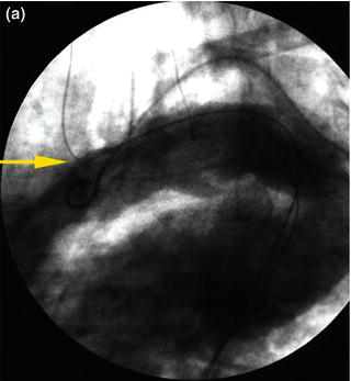
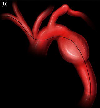
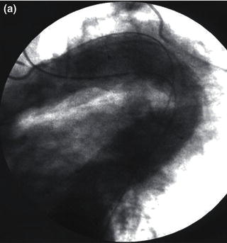
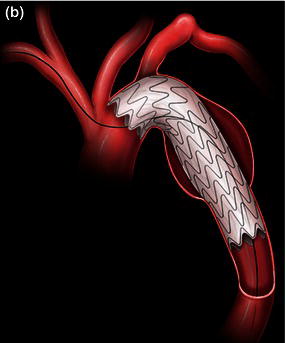
In tortuous aorta, the use of the brachio-femo ral wire may be required to aid advancement and deployment of an endograft. Deployment of an endoluminal graft in a tortuous aorta may be difficult, requiring the use of a brachio-femoral wire (Fig. 1.2). Use of brachio-femoral access wires can help straighten the most angulated of vessels. The presence of a tortuous aorta requires brachio-femoral access to deploy an endoluminal graft (Fig. 1.3). Brachial access is obtained by a percutaneous retrograde puncture of the right brachial artery with an 18 gauge needle or a micropuncture needle. An extra long 450 cm, 0.035 inch angled glide wire is advanced through the brachial sheath into the tortuous thoracic aorta, snared and pulled out through the groin sheath. The technique requires that a protective guiding catheter be placed over the brachial artery to protect the subclavian artery from injury. It is important to have at least a 260 cm long wire and constant tension must be placed on both ends of the wire as the delivery sheath is passed into the aorta [2,3]. By pulling on both ends of the wire an endoluminal graft can be advanced up into the tortuous arch aorta with precise deployment of the endoluminal graft.
Fig. 1.1 (a) A retrograde percutaneous puncture of the brachial artery with (b) the placement of an introducer sheath.

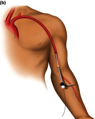
Fig. 1.2 (a) Angiogram and (b) illustration demonstrating advancement of a brachio-femoral wire in a tortuous thoracic aorta.
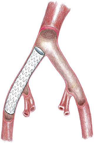
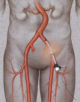
An endoconduit is an alternative percutaneous technique that can be used to deliver a thoracic endograft in a patient with a small, calcified, or tortuous vessel instead of the conventional ilio-femoral conduit (Fig. 1.4). This technique can be applied in high-risk patients who have a relative contraindication to conventional open surgical techniques under general anesthesia. The endoluminal conduit technique allows aggressive balloon dilation of long segments of ilio-femoral stenosis without the risk of vessel rupture. The endoluminal graft conduit can be custom-assembled using graft diameters of at least 8 mm and preferably 10 mm, and can be back-loaded into a delivery sheath and deployed via a femoral arteriotomy into the common iliac artery covering the origin of the internal iliac artery [2,4].
Fig. 1.3 (a) Angiogram and (b) illustration demonstration of deployment of a thoracic endograft using a brachio-femoral wire approach.
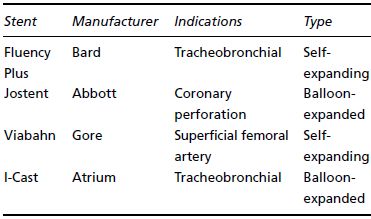
Retrograde percutaneous access of the common femoral artery is performed with an 18 gauge needle in the usual fashion and a 0.035 inch glide wire is advanced under fluoroscopic guidance into the distal thoracic aorta after heparin is administered. A 9 Fr sheath is then exchanged for the needle. A retrograde angiographic picture of the iliac vessels is performed noting the size, tortuosity, and calcification. The presence of a small, or severely calcific or tortuous, iliac vessel may preclude the introduction of a delivery sheath (Fig. 1.5). An attempt may be made to pass the delivery sheath, and if any resis tance is noted the patient would require a retroperitoneal conduit or an endoconduit. Using the existing 9 Fr sheath, balloon angioplasty can be performed to gently dilate the vessel; subsequently, an endoluminal graft, most commonly (Viahbahn; W.L. Gore & Associates, Flagstaff, AZ), or an I-Cast stent-graft (Atrium Medical, Hudson, NH) (Table 1.1) is deployed across the common iliac and external iliac artery covering the hypogastric vessels (Fig. 1.6). Post-deployment balloon angioplasty is subsequently performed with a balloon to expand the endoluminal graft; this technique has been referred to as cracking and paving. The 9 Fr sheath is subsequently exchanged to a 20–24 Fr delivery sheath that is required to deliver the thoracic endoluminal graft.
Fig. 1.4 Illustration of thoracic aorta.
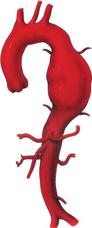
Fig. 1.5 Angiogram demonstrating a small, tortuous left iliac artery.
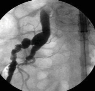
Table 1.1 Commercially available covered stents used for peripheral indications.
Most right-handed physicians will prefer the patient’s right groin for femoral access, although both groins should be prepped in case of inaccessibility. After the pulse is identified, the inguinal ligament is found by tracing a line between the anterior iliac spine and the pubic tubercle. Often, especially in obese individuals, the inguinal crease is inferior to this landmark. Access should be made below the inguinal ligament corresponding to the common femoral artery. One will find that if access is made too high, corresponding with the external iliac artery, hemostasis is difficult to achieve with manual pressure. In this case hemorrhage can occur after removal of devices and a retroperitoneal hematoma can develop. This is often insidious in onset. In addition, the risk of pseudoaneurysm formation is higher in an external iliac stick, again because direct manual pressure cannot be applied this superiorly.
Fig. 1.6 Deployment of an endoconduit.
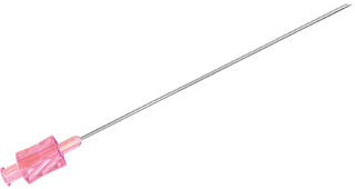
A properly equipped endovascular suite will allow fluoroscopic imaging of the groin to identify all anatomic landmarks. In addition to surface landmarks, most physicians use the medial half of the femoral head to guide femoral artery access; this ensures common femoral artery entry and avoids the complications of a higher stick. It is also useful in the pulseless femoral artery. Most vascular access kits include an 18 gauge straight angiographic entry needle (Fig. 1.7). This is inserted using the dominant hand at a 45° angle while using the non-dominant hand for guidance using a Seldinger technique. Percutaneous arterial femoral access is usually obtained by the Seldinger technique. A careful palpation of the femoral pulse is performed and a beveled needle (usually 18 gauge) is introduced through the arterial wall. The needle is slowly withdrawn until return of arterial blood is achieved, signifying the intraluminal position of the needle. The presence of poor blood flow signifies that the tip is misplaced or the needle is too close to the arterial wall. A soft-tip angled 0.035 inch guide wire is then introduced through the central lumen of the needle under fluoroscopic guidance (Fig. 1.8). Progress of the guide wire intraluminally should be monitored with fluoroscopy to avoid diversion into branched vessels and dissection of the vessel. The presence of resistance in passing a guide wire signifies possible misdirection or dissection of the vessel wall. In instances where the vessel may be small, calcified, or tortuous, a smaller access needle may be desirable. A micropuncture kit (Cook Medical, Bloomington, IN) exists which includes a 21 gauge needle for initial access.
Fig. 1.7 An 18 gauge 7 cm Cook percutaneous needle.
Once access is achieved a small nick is made in the skin with a no. 11 blade and a dilator, and an introducer sheath is then advanced over the glide wire with the dilator preceding the introducer sheath by a few inches, again under fluoroscopic visualization (Fig. 1.9). Once the introducer sheath is positioned the dilator is removed. A hemostatic valve at the end of the introducer sheath prevents leakage of blood. The introducer sheath permits various guide wires, balloons, and stents to be introduced safely within the arterial lumen. The introducer sheath can subsequently be upgraded to a larger delivery sheath for the deployment of an endograft. In patients with a femoral-to-femoral graft, percutaneous access can be performed either through the inflow limb of the femoral–femoral graft or above the inflow limb.
Fig. 1.8 Introduction of an angled glide wire through the 18 gauge needle.
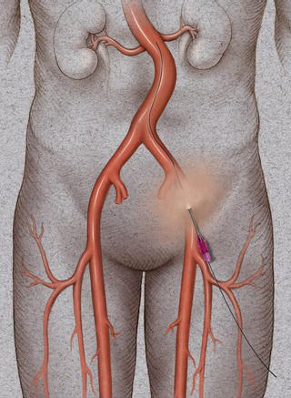
Fig. 1.9 Introduction of a 9 Fr 11 cm sheath in a retrograde percutaneous fashion through the common femoral artery.
In patients with significant peripheral vascular disease, imaging studies using an angiogram or a CT scan are necessary for sizing and determination of calcification, as well as tortuosity of vessels which would make the femoral delivery of an endograft hazardous. The introduction of large sheaths in femoral vessels that are calcified, tortuous, small caliber, or a combination are predisposed to rupture.
The common femoral artery is usually exposed for retrograde cannulation and the introduction of various large-sized introducer sheaths, balloons, self-expandable and balloon-expandable stents, and endoluminal grafts.
A curvilinear incision is made two finger-breaths above the groin crease and over the palpable femoral pulse. The incision is carried down to the femoral sheath. Retraction is performed with a Gelpe retractor or a Wietlander retractor. The femoral sheath is incised to expose the common femoral artery. Heavy silk sutures are passed circumferentially round the various side branches. Adequate mobilization of the common femoral artery is desired to be able to achieve adequate proximal and distal control of the vessel. A Rummel tourniquet is applied to the common femoral artery to serve as a proximal control.
The fluoroscopic C-arm is then positioned over the exposed femoral artery. Retrograde cannulation of the common femoral artery is performed with a beveled needle (18 gauge) until pulsatile blood flow is visualized. A soft-tip angled guide wire is advanced in the vessels under fluoroscopy. The needle is then exchanged for a selected sized dilator and introducer sheath. The dilator is removed and the sheath flushed with heperanized saline. Open cannulation or retrograde percutaneous access can be similarly performed in the contralateral common femoral artery (Fig. 1.10a).
Once the procedure is completed all wires and sheaths are removed under fluoroscopic guidance to ensure no injury is caused to the vessel wall. The arteriotomy is then closed with a 5-0 prolene suture after proximal and distal control is achieved (Fig. 1.10b).
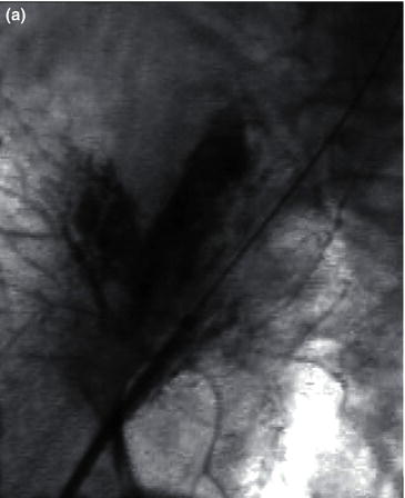
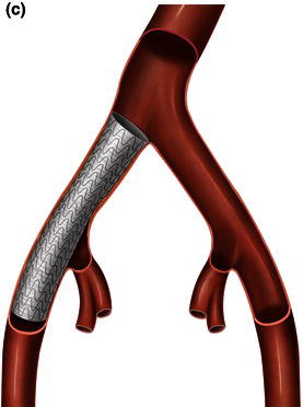
Attempts to introduce a delivery sheath in a small, tortuous, or calcified artery, or a combination, will lead to rupture of the access vessel typically at the junction of the external and internal iliac artery or at the aorto-iliac bifurcation. Rupture of an access vessel should be suspected if there is a drop in the blood pressure during advancement of the delivery sheath or during removal of the delivery sheath. The guide wire should be maintained at all times prior to removal of a delivery sheath and an iliac angiogram performed prior to removal of the introducer sheaths to confirm extravasation of contrast (Fig. 1.11a). Once rupture is confirmed, an appropriate length and diameter of a covered stent-graft should be chosen (Fig. 1.11b) and deployed across the area of rupture (Fig. 1.11c). In most instances coverage of the hypogastric artery is required.
The introduction of guide wires, introduction and delivery sheaths may result in dissection of the access vessels. Similarly, balloon angioplasty of calcified access vessels may also result in a dissection flap of the resulting access vessels. Once a dissection is identified on angiogram, gentle balloon angioplasty may be performed to seal the dissecting septum or a covered or uncovered balloon-deployable stent may be used to seal off the dissection. Failure to recognize a dissection may result in thrombosis of the access vessels with resulting ischemia of the involved lower extremity [2].
Fig. 1.10 (a) Open retrograde cannulation of the right common femoral artery and percutaneous retrograde cannulation of the left common femoral artery. (b) Closure of the arteriotomy after removal of the guide wire and introduction sheath.

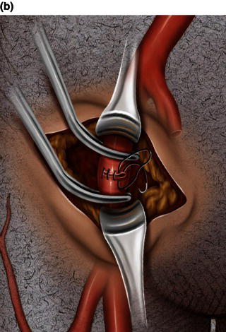
Fig. 1.11 (a) Angiogram demonstrating rupture of the right external iliac artery. (b) A covered stent-graft used to exclude the site of rupture. (c) A covered stent-graft deployed across a ruptured iliac artery.

Safe performance of thoracic endovascular procedures including thoracic stent-grafting of aneurysms, dissections, retrograde delivery of transcatheter aortic valves, and other complex endovascular procedures for structural heart disease requires zero tolerance for major access-related complications. Thorough preoperative planning, understanding the pathology of aorto-iliac occlusive disease, advanced endovascular skills, and ability to perform an iliac conduit via a retroperitoneal approach are necessary to achieve excellent results. Furthermore, deliverability of complex thoracic endovascular devices through tortuous anatomy or old graft material may be improved by the more proximal access provided by an iliac conduit [5].
Patients undergoing thoracic aortic endografting require access with devices ranging between 18 and 25 Fr caliber. The external iliac artery is the size-limiting segment and, depending on the size of sheath required, a minimum diameter of 9 mm may be necessary for safe access via the common femoral arteries. Patients with calcified, tortuous, or small vessel size or a combination (Fig. 1.12) may not be candidates for delivery of these large sheaths through femoral arterial access and any attempts to deliver an introducer sheath or an endoluminal graft may result in an increased risk of iliac artery rupture or the “artery on a stick” phenomenon (Fig. 1.13). Iliac artery diameters of 7.6–9.2 mm are required to deliver most devices through the femoral approach safely without the requirement of a conduit (Tables 1.2 and 1.3). Retroperitoneal exposure with construction of a 10 mm ilio-femoral conduit permits delivery of large sheaths in patients with tortuous, calcified and small iliac vessels or vessels with severe ilio-femoral vascular occlusive disease.
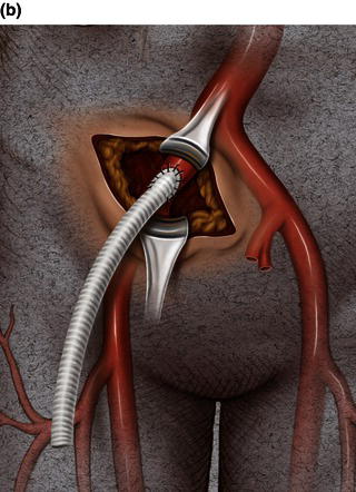
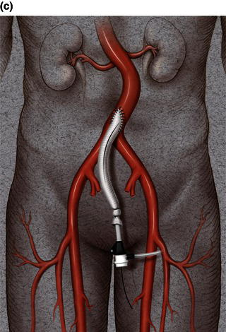
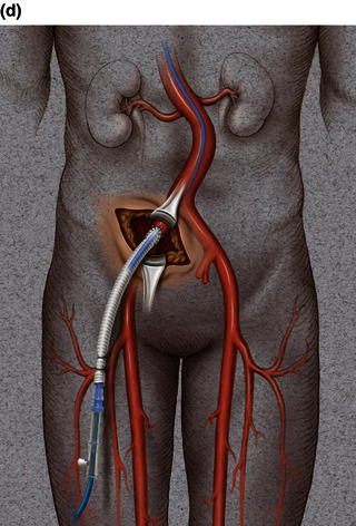
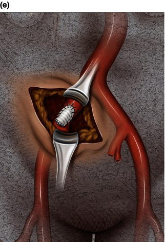
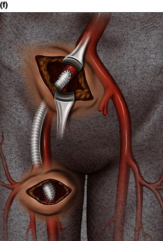
A 15 cm semi-lunar right flank incision is made four finger-breaths above the groin crease. Division of the external oblique, internal oblique and transversus abdominus muscles is performed in the direction of their fibers. The extraperitoneal fascia and peritoneum are then retracted medially and dissection is carried out in the avascular plane of the retroperitoneum down to the level of the psoas muscle. All of the abdominal contents are then retracted medially with the help of a handheld retractor or an Omni retractor, providing excellent exposure of the lower infrarenal aorta, common iliac artery, and iliac bifurcation. The right common iliac artery along with the hypogastric and the external iliac artery are identified and mobilized (Fig. 1.14a). Care is taken to spare the right urether which crosses the common iliac artery before diving deep into the pelvis. A Rummel tourniquet is applied to control the proximal common iliac artery, the external iliac artery, and origin of the hypogastric artery; alternatively, vascular clamps could be applied for control. Heparin is usually given to the patient prior to clamping the vessels. An arteriotomy is made on the common iliac artery with a no. 11 blade and extended with Pott’s scissors close to the bifurcation of the hypogastric artery and the external iliac artery. A 10 mm conduit is then sewn in an end-to-side fashion using 5-0 prolene sutures (Fig. 1.14b). The 10 mm graft is subsequently tunneled through the retroperitoneal space beneath the inguinal ligament and brought out through the groin incision used to expose the common femoral artery. The graft is subsequently flashed and clamped at the groin incision with the Rummel tourniquets released from the common iliac artery, external iliac artery, and hypogastric artery. The 10 mm conduit is subsequently looped with a Rummel tourniquet and ready to be punctured with an 18 gauge needle for access and introduction of a guide wire and an introducer sheath (Fig. 1.14c). The introducer sheath is subsequently exchanged for a device sheath, which is advanced into the distal aorta (Fig. 1.14d). The endoluminal graft is then introduced into the delivery sheath and deployed to the target area. Wires and sheaths are removed from the 10 mm conduit and the conduit is clamped.
The conduit can either be trimmed to the appropriate length and the conduit tied off as a stump (Fig. 1.14e) or the distal end of the conduit can be sewn to the more distal iliac system in an end-to-end fashion as an interposition graft. Or, more commonly, the conduit can be brought to the groin by tunneling the conduit under the inguinal ligament and performing either an end-to-end anastomosis or an ilio-femoral conduit. The ilio-femoral conduit is performed by making an arteriotomy on the adequately exposed common femoral artery after adequate proximal and distal control is achieved. An end-to-side anastomosis is constructed with a 5-0 prolene suture with adequate flushing maneuvers performed prior to completion of the anastomosis (Fig. 1.14f). The ilio-femoral conduit is best for patients who may require further intervention for diffuse thoracic aneurysmal disease as the conduit may be reused through a simple infrainguinal incision in the future. The groin incision is approximated in layers. The right flank incision is irrigated, a 10 Fr Jackson–Pratt drain is placed in the retroperitoneal space and the incision closed in layers. The same technique can be applied to the infrarenal aorta and thoracic aorta. Similarly, end-to-side grafting of a conduit to the axillary artery, as described elsewhere, to facilitate deep hypothermic circulatory arrest also provides excellent access to the thoracic aorta via the innominate [2].
Fig. 1.12 Illustrations demonstrating calcified, tortuous, small tortuous, and small calcified tortuous iliac arteries which are contraindication for femoral access, requiring a retroperitoneal exposure with sewing of an iliac conduit for delivery of the endograft. (a) Calcified iliac artery. (b) Tortuous iliac artery. (c) Small tortuous iliac artery. (d) Small calcified tortuous iliac artery.
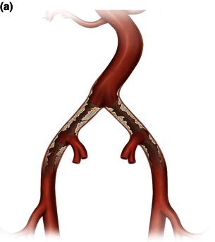
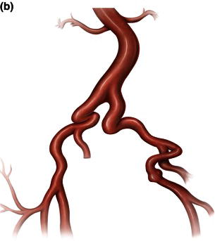
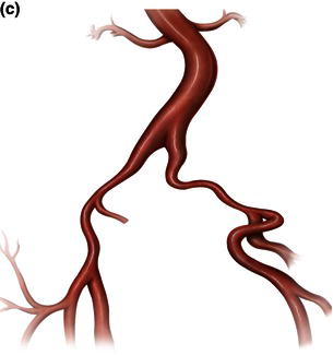
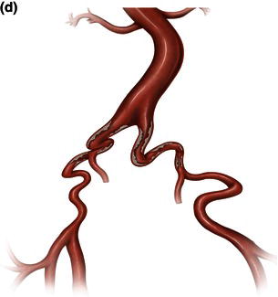
Fig. 1.13 Artery on a stick.
Table 1.2 Graft and delivery sheath sizes for descending thoracic aortic stent-grafts currently available in the United States.
| Endograft | Graft size available (diameter) | Sheath size required (diameter) |
| Gore TAG | 26–40 mm | 20–24 Fr (7.6–9.2 mm) |
| Zenith TX1/TX2 | 28–42 mm | 20–22 Fr (7.6–8.3 mm) |
| Talent | 22–46 mm | 22–25 Fr |
Table 1.3 Recommended iliac diameters for the introduction of Gore sheaths.
| Size (Fr) | ID (mm) | OD (mm) |
| 20 | 6.7 | 7.6 |
| 22 | 7.3 | 8.3 |
| 24 | 8.1 | 9.1 |
ID, inner diameter; OD, outer diameter.
Fig. 1.14 (a) Retroperitoneal exposure. (b) A 10 mm conduit sewn to the iliac artery. (c) Conduit brought out of the incision with cannulation of the conduit with an introducer sheath. (d) Introducer sheath exchanged for a device sheath and advanced through the 10 mm conduit to the distal abdominal aorta. (e) Ligation of a 10 mm conduit. (f) Conduit tunneled and sewn to the femoral artery as an ilio-femoral conduit.

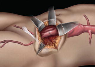
A 15 cm semi-lunar right flank incision is made four finger-breaths above the groin crease. Division of the external oblique, internal oblique, and transversus abdominus muscle is performed. The peritoneum is identified and gently retracted medially with the help of a handheld retractor. The common iliac artery along with the hypogastric and external iliac artery are identified and mobilized. Care is taken to spare the right urether which crosses the common iliac artery before diving deep into the pelvis. A Rummel tourniquet is applied to control the proximal common iliac artery, the external iliac artery, and origin of the hypogastric artery; alternatively, vascular clamps could be applied for control. Heparin is usually given to the patient prior to clamping the vessels. An 18 gauge needle is used to access the common iliac artery close to the hypogastric artery bifurcation and a guide wire and an introducer sheath are advanced. The introducer sheath is subsequently exchanged for a device sheath, which is advanced into the distal aorta (Fig. 1.15). The endoluminal graft is then introduced into the delivery sheath and deployed to the target area. Wires and sheaths are removed and the arteriotomy repaired in a standard fashion (Fig. 1.16). The flank incision is irrigated, a 10 Fr Jackson–Pratt drain is placed in the retroperitoneal space, and the incision closed in layers.
Fig. 1.15 Direct introduction of the device sheath through the common iliac artery through a retroperitoneal exposure.
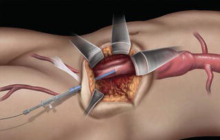
Fig. 1.16 Direct repair of the iliac artery.
References
1 Schneider PA. Endovascular Skills: Guidewire and Catheter Skills for Endovascular Surgery, 3rd edn. New York: Informa Healthcare, 2008.
2 Diethrich EB, Ramaiah VG, Kpodonu J, et al. Endovascular and Hybrid Management of the Thoracic Aorta. A case-based approach, 1st edn. Oxford: Wiley-Blackwell, 2008.
3 Kpodonu J, Rodriguez JA, Ramaiah VG, et al. Use of the right brachio-femoral wire approach to manage a thoracic aortic aneurysm in an extremely angulated and tortuous aorta with an endoluminal stent graft. Interact CardioVasc Thorac Surg 2008; 7:269–71.
4 Kpodonu J, Rodriguez JA, Ramaiah VG, et al. Cracking and paving: a novel technique to deliver a thoracic endograft despite ilio-femoral occlusive disease. J Card Surg 2009; 24(2):188–90.
5 Abu-Ghaida AM, Clair DG, Greenberg RK, et al. Broadening the applicability of endovascular aneurysm repair: the use of iliac conduits. J Vasc Surg 2002; 36:111–17.
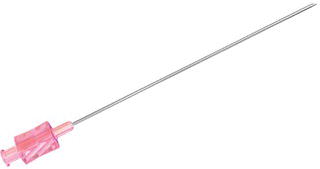
Endovascular procedures require the use of a percutaneous needle. Needles come in a variety of lengths and gauges. Each needle contains two parts: the hub used when attaching the needle to the syringe and the cannula, which is the hollow shaft of the needle. The most common gauge used is the 18 gauge needle (Fig. 2.1). The 18 gauge needle will accommodate a .035 inch guide wire. The length of needles varies between 2 and 3.5 inches. Other accessories include micropuncture sets and smart needles.
Fig. 2.1 18 gauge 7 cm Cook percutaneous needle.
These devices dilate the tract the needle has created, allowing large devices such as catheters and sheaths to be introduced into the vessel. They are placed over the guide wire that was introduced through the original puncture needle. Vessel dilators are measured in French sizes (1 Fr ≈ 0.33 mm) and are most commonly 15–20 cm in length. “Serial dilation” can be necessary when attempting to introduce large diameter sheaths, particularly with patients that have scar tissue build up in the common femoral artery (CFA) area. It is important not to overdilate the tract. Overdilating can allow blood to leak around your catheter or sheath, not allowing you to gain hemostatic control of the vessel. Dilator sets may vary from 4 to 22 Fr × 20 cm (Fig. 2.2).
Guide wires are used to access the vessel through the percutaneous needle [1]. In addition, they are used to help steer catheters and devices through the vascular anatomy. Guide wires are manufactured in several different ways: they are either solid steel core wires, or the steel core can be wrapped in a thin steel coil. The core can also be encased in a polymer-type jacket. Recently they have started using nitinol metal for the inner core material. Guide wires usually have a floppy tip with a stiff body. The tip configuration usually includes angled tips, straight tips, J-tips, and shapeable tips. The diameters of the wires are measured in thousandths of an inch, ranging from 0.014 to 0.038 inches. Lengths are measured in centimeters and can range from 80 to 300 cm. However, some specialty wires can come in lengths up to 450 cm.
Fig. 2.2 Dilator sets.
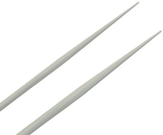
Fig. 2.3 Ultrastiff guide wires used in thoracic endografting.
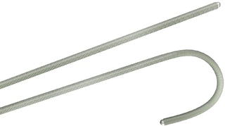
Some guide wires may have a hydrophilic coating, making them slippery when wet. Hoag Hospital’s primary workhorse guide wire is the 0.035 inch Terumo angled glide wire. This wire has a hydrophilic coating. It is constructed with a center core of superelastic metal alloy that tapers to a soft flexible tip. The kink-resistant core is coated with a polyurethane jacket. This jacket is bonded with a hydrophilic polymer that becomes slick when saline has been applied. There are many guide wire manufacturers, with hundreds, possibly thousands, of wires to choose from (Fig. 2.3). The wire selection is dependent on the location of the lesion, the tortuousity of the vessel, and the physician’s preference.
Sheaths are hemostatic conduits inserted into the vessel (Fig. 2.4). They allow the passage of guide wires, catheters, and interventional devices. The sheath allows these to be passed in and out of the body without damaging the vessel and reduces the blood loss. Some sheaths may have a braided wire construction to reduce kinking in acute angles. They may have a radiopaque tip for visualization under fluoroscopy. Sheaths are measured by the inner diameter in French sizes. They are universally color coated (Box 2.1). They range in sizes from 4 to 24 Fr. Larger sized sheaths may require the surgeon to “cut down” and expose the CFA in order to repair the large arteriotomy post procedure.
Fig. 2.4 Introducer sheaths commonly used in introducing balloons, catheters, and wires for thoracic endografting.
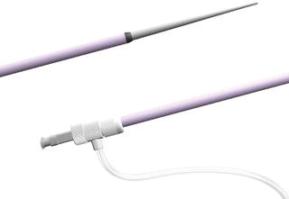
Catheters have three primary purposes: to delivery contrast for arteriography images, to assist in directing wires through target lesions needing intervention, and to give shaped support when trying to deliver devices to these target lesions (Box 2.2). Catheters are measured by the outer diameter in French sizes. The diagnostic catheters are of 4–5 Fr diameters and are used to help maneuver guide wires through the vascular anatomy and to deliver contrast for angiograms (Fig. 2.5). The guide catheters are 6–12 Fr in diameter and are used to assist in the delivery of the interventional devices, such as stents and balloons. These catheters come in hundreds of shapes and lengths; they come in braided and non-braided construction. They have special features like hydrophilic coatings, radiopaque tips, and radiopaque markers used to help determine lesion lengths.
Fig. 2.5 Guiding catheters used in thoracic endografting.
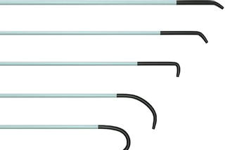
Fig. 2.6Fig. 2.7