

Contents
Editor’s preface to the Manchester Physics Series
Foreword
Author’s preface to second edition
Flow Diagram
CHAPTER 1 CRYSTAL STRUCTURE
1.1 Introduction
1.2 Elementary Crystallography
1.3 Typical Crystal Structures
1.4 X-ray Crystallography
1.5 Quasi-crystals
1.6 Interatomic Forces
CHAPTER 2 CRYSTAL DYNAMICS
2.1 Introduction
2.2 SoundWaves
2.3 Lattice Vibrations of One-dimensional Crystals
2.4 Lattice Vibrations of Three-dimensional Crystals
2.5 Phonons
2.6 Heat Capacity from Lattice Vibrations
2.7 Anharmonic Effects
2.8 Thermal Conduction by Phonons
CHAPTER 3 FREE ELECTRONS IN METALS
3.1 Introduction
3.2 The Free Electron Model
3.3 Transport Properties of the Conduction Electrons
CHAPTER 4 THE EFFECT OF THE PERIODIC LATTICE POTENTIAL—ENERGY BANDS
4.1 Nearly Free Electron Theory
4.2 Classification of Crystalline Solids into Metals, Insulators and Semiconductors
4.3 The Tight Binding Approach
4.4 Band Structure Effective Masses
CHAPTER 5 SEMICONDUCTORS
5.1 Introduction
5.2 Holes
5.3 Methods of Providing Electrons and Holes
5.4 Absorption of Electromagnetic Radiation
5.5 Transport Properties
5.6 Non-equilibrium Carrier Densities
CHAPTER 6 SEMICONDUCTOR DEVICES
6.1 Introduction
6.2 The p–n Junction with Zero Applied Bias
6.3 The p–n Junction with an Applied Bias
6.4 Other Devices Based on the p-n Junction
6.5 Metal–oxide–semiconductor technology and the MOSFET
6.6 Molecular Beam Epitaxy and Semiconductor Heterojunctions
CHAPTER 7 DIAMAGNETISM AND PARAMAGNETISM 198
7.1 Introduction
7.2 Paramagnetism
7.3 Diamagnetism
CHAPTER 8 MAGNETIC ORDER
8.1 Introduction
8.2 The Exchange Interaction
8.3 Ferromagnetism
8.4 The Néel Model of Antiferromagnetism
8.5 Spin Waves
8.6 Other Types of Magnetic Order
8.7 Ferromagnetic Domains
CHAPTER 9 ELECTRIC PROPERTIES OF INSULATORS
9.1 Dielectrics
9.2 Pyroelectric Materials
9.3 Piezoelectricity
CHAPTER 10 SUPERCONDUCTIVITY
10.1 Introduction
10.2 Magnetic Properties of Superconductors
10.3 The London Equation
10.4 The Theory of Superconductivity
10.5 Macroscopic Quantum Phenomena
10.6 High-temperature Superconductors
CHAPTER 11 WAVES IN CRYSTALS
11.1 Introduction
11.2 Elastic Scattering of Waves by a Crystal
11.3 Wavelike Normal Modes—Bloch’s Theorem
11.4 Normal Modes and the Reciprocal Lattice
CHAPTER 12 SCATTERING OF NEUTRONS AND ELECTRONS FROM SOLIDS
12.1 Introduction
12.2 Comparison of X-rays, Neutrons and Electrons
12.3 Neutron Scattering Techniques
12.4 Determination of Phonon Spectra
12.5 Magnetic Scattering
12.6 Electron Scattering
CHAPTER 13 REAL METALS
13.1 Introduction
13.2 Fermi Surfaces
13.3 Electron Dynamics in a Three-dimensional Metal
13.4 Experimental Determination of the Fermi Surface
13.5 Why do Electrons Behave Independently?
13.6 Electromagnetic Waves in Metals
CHAPTER 14 LOW-DIMENSIONAL SYSTEMS
14.1 Introduction
14.2 The Two-dimensional Electron Gas
14.3 The Quantum Hall Effect
14.4 Resonant Tunnelling Devices
APPENDIX A Coupled probability amplitudes
APPENDIX B Electric and magnetic fields inside materials
APPENDIX C Quantum mechanics of an electron in a magnetic field
APPENDIX D The exchange energy
Bibliography
Solutions to problems
Index
Table of Constants

Copyright © 1974 by John Wiley & Sons, Ltd, The Atrium, Southern Gate,
Chichester, West Sussex P019 8SQ, England
Telephone (+ 44) 1243 779777
Email (for orders and customer service enquiries): cs-books@wiley.co.uk
Visit our Home Page www.wileyeurope.com or www.wiley.com
First edition 1974
Second edition 1991
Reprinted June and November 1994, July 1995, August 1996, February 1997, February 1998 and
February 1999
Reprinted with corrections December 2000, November 2001, April 2003, August 2004, April 2005,
October 2006, December 2007, October 2008, February 2010
All Rights Reserved. No part of this publication may be reproduced, stored in a retrieval system or transmitted in any form or by any means, electronic, mechanical, photocopying, recording, scanning or otherwise, except under the terms of the Copyright, Designs and Patents Act 1988 or under the terms of a licence issued by the Copyright Licensing Agency Ltd, 90 Tottenham Court Road, London WIT 4LP, UK, without the permission in writing of the Publisher, with the exception of any material supplied specifically for the purpose of being entered and executed on a computer system, for exclusive use by the purchaser of the publication.
Neither the author(s) nor John Wiley & Sons, Ltd accept any responsibility or liability for loss or damage occasioned to any person or property through using the material, instructions, methods or ideas contained herein, or acting or refraining from acting as a result of such use. The author(s) and Publisher expressly disclaim all implied warranties, including merchantability of fitness for any particular purpose.
Other Wiley Editorial Offices
John Wiley & Sons Inc., 111 River Street, Hoboken, NJ 07030, USA
Jossey-Bass, 989 Market Street, San Francisco, CA 94103-1741, USA
Wiley-VCH Verlag GmbH, Boschstr. 12, D-69469 Weinheim, Germany
John Wiley & Sons Australia Ltd, 33 Park Road, Milton, Queensland 4064, Australia
John Wiley & Sons (Asia) Pte Ltd, 2 Clementi Loop #02-01, Jin Xing Distripark, Singapore 129809
John Wiley & Sons (Canada) Ltd, 22 Worcester Road, Etobicoke, Ontario M9W 1L1
Wiley also publishes its books in a variety of electronic formats. Some content that appears in print may not be available in electronic books.
Library of Congress Cataloging-in-Publication Data
Hook, J. R. (John R.)
Solid state physics/J. R. Hook, H. E. Hall.—2nd ed.
p. cm.—(The Manchester physics series)
Rev. ed. of: Solid state physics/H. E. Hall, 1st ed. 1974.
Includes bibliographical references and index.
ISBN 0 471 92804 6 (cloth)—ISBN 0 471 92805 4 (paper)
1. Solid state physics. I. Hall, H. E. (Henry Edgar), 1928–
II. Hall, H. E. (Henry Edgar), 1928– Solid state physics.
III. Title. IV. Series.
QC176.H66 1991
530.481—dc20
90–20571
CIP
British Library Cataloguing in Publication Data
Hook, J. R.
Solid state physics.
1. Solids. Structure & physics properties
I. Title II. Hall, H. E. (Henry Edgar) III. Series
530.41
ISBN 978 0 471 92804 1 (hbk)
ISBN 978-0471-92805-8 (pbk)
To my family in partial compensation for taking so much of
my time away from them
The Manchester Physics Series is a series of textbooks at first degree level. It grew out of our experience at the Department of Physics and Astronomy at Manchester University, widely shared elsewhere, that many textbooks contain much more material than can be accommodated in a typical undergraduate course; and that this material is only rarely so arranged as to allow the definition of a shorter self-contained course. In planning these books we have had two objectives. One was to produce short books: so that lecturers should find them attractive for undergraduate courses; so that students should not be frightened off by their encyclopaedic size or their price. To achieve this, we have been very selective in the choice of topics, with the emphasis on the basic physics together with some instructive, stimulating and useful applications. Our second objective was to produce books which allow courses of different lengths and difficulty to be selected, with emphasis on different applications. To achieve such flexibility we have encouraged authors to use flow diagrams showing the logical connections between different chapters and to put some topics in starred sections. These cover more advanced and alternative material which is not required for the understanding of latter parts of each volume.
Although these books were conceived as a series, each of them is self-contained and can be used independently of the others. Several of them are suitable for wider use in other sciences. Each Author's Preface gives details about the level, prerequisites, etc., of his volume.
The Manchester Physics Series has been very successful with total sales of more than a quarter of a million copies. We are extremely grateful to the many students and colleagues, at Manchester and elsewhere, for helpful criticisms and stimulating comments. Our particular thanks go to the authors for all the work they have done, for the many new ideas they have contributed, and for discussing patiently, and often accepting, the suggestions of the editors.
Finally, we would like to thank our publishers, John Wiley & Sons Ltd, for their enthusiastic and continued commitment to the Manchester Physics Series.
D. J. Sandiford
F. Mandl
A. C. Phillips
February 1997
Author’s preface to second edition
I accepted the invitation of the editors of the Manchester Physics Series to write a second edition of Solid State Physics for two main reasons. Firstly I felt that, although the approach adopted in the first edition had much to commend it, some re-ordering and simplification of the material was required to make the book more accessible to undergraduate students. Secondly there was a need to take account of some of the important developments that have occurred in solid state physics since 1973.
To achieve re-ordering and simplification it has been necessary to rewrite most of the first edition. A major change has been to introduce the idea of mobile electron states in solids through the free electron theory of metals rather than through the formation of energy bands by overlap of atomic states on neighbouring atoms. The latter approach was used in the first edition because it could be applied first to the dilute electron gas in semiconductors where an independent particle model might be expected to work. Although this was appealing to the experienced physicist, it proved difficult to the undergraduate student, who was forced to assimilate too many new ideas at the beginning. One feature of the first edition that I have retained is to delay for as long as possible a formal discussion of the reciprocal lattice and Brillouin zones in a three-dimensional crystal. Although these concepts provide an elegant general framework for describing many of the properties of crystalline solids, they are, like Maxwell’s equations in electromagnetism, more likely to be appreciated by students if they have met some of the ideas earlier in a simpler context. The use of the formal framework is avoided in the early chapters by using one- and two-dimensional geometries whenever necessary.
To take account of recent developments the amount of material on semiconductor physics and devices has been substantially increased, a chapter has been added on the two-dimensional electron gas and quantum Hall effect, and sections on quasi-crystals, high-Tc superconductors and the use of electrons to probe surfaces have been included. A chapter on the electrical properties of insulators has also been added.
I have tried to conform to the aim of the Manchester Physics Series by producing a book of reasonable length (and thus cost), from which it is possible to define self-contained undergraduate courses of different length and difficulty. The problem with solid state physics in this context is that it contains many diverse topics so that many quite different courses are possible. I have had to be very selective therefore in my choice of subjects, which has been strongly influenced by the third year undergraduate solid state physics courses at Manchester. We currently have a basic course of 20 lectures, which is given at two levels; the courses cover material from Chapters 1–5 of this book and the higher level course also incorporates appropriate sections of Chapters 11–13. A further course of 20 lectures on selected topics in solid state physics currently covers magnetism, superconductivity and ferroelectricity (Chapters 7–10). The flow diagram inside the front cover can be used as an aid to the design of courses based on this book.
Important subjects that are not covered in this book are crystal defects and disordered solids. I would have liked to include a chapter on each of these topics but would have exceeded the length limit set by the publishers and editors had I done so.
Like the first edition, this book presupposes a background knowledge of properties of matter (interatomc potentials and their relation to binding energies and elastic moduli, kinetic theory), quantum mechanics (Schrodinger’s equation and its solution to find energy eigenvalues and eigenfunctions), electricity and magnetism (Maxwell’s equations and some familiarity with electric and magnetic fields in matter) and thermal physics (the Boltzmann factor and the Fermi and Bose distributions). Books in which this background information can be found are listed in the bibliography along with selected general reference books on solid state physics and some books and articles that provide further information on specific topics.
This book includes some more advanced and detailed material, which can be omitted without loss of continuity. Complete sections in this category are identified by starring and parts of sections are printed on a grey background.
The use of bold type for a technical term in the text, normally when the term is first encountered, indicates that a definition or explanation of the term can be found there. Italic type is used for emphasis.
I am very grateful to David Sandiford and Henry Hall for their helpful advice and constructive criticism. I would also like to thank Manchester undergraduate Colin Lally, who read the manuscript from the point of view of a prospective consumer; his reaction reassured me that the level was appropriate. Ian Callaghan’s draughtmanship and photography was invaluable in producing many of the figures, and my son James helped willingly with some of the more mundane manuscript-preparation tasks.
September 1990
JOHN HOOK
Foreword
The story of the creation was told in 200 words. Look it up if you don't believe me.—Edgar Wallace
When the time came to consider a second edition of Solid State Physics I felt that I had already said what I had to say on the subject in the first edition. I also felt that the book was rather too idiosyncratic for many students. For these reasons I thought it would be better if the revision and updating were undertaken by another hand, and the editors shared this view.
We therefore approached Dr John Hook, a friend and colleague for many years, and I think the result justifies the decision. The new edition is, in my opinion, a substantial improvement on the old one, but it would not have occurred to me to write it like that.
September 1990
Henry Hall
The Manchester Physics Series
General Editors
D. J. SANDIFORD: F. MANDL: A. C. PHILLIPS
Department of Physics and Astronomy, Faculty of Science, University of Manchester
| Properties of Matter: | B. H. Flowers and E. Mendoza |
| Statistical Physics: Second Edition |
F. Mandl |
| Electromagnetism: Second Edition |
I. S. Grant and W. R. Phillips |
| Statistics: | R. J. Barlow |
| Solid State Physics: Second Edition |
J. R. Hook and H. E. Hall |
| Quantum Mechanics: | F. Mandl |
| Particle Physics: Second Edition |
B. R. Martin and G. Shaw |
| The Physics of Stars: Second Edition |
A. C. Phillips |
| Computing for Scientists: | R. J. Barlow and A. R. Barnett |
| Nuclear Physics: | J. S. Lilley |
FLOW DIAGRAM

Solid lines indicate essential prerequisites.
Dashed arrows indicate some assumption of material from a previous chapter.
Cover photography Visible light from a semiconductor laser developed at Philips Opteoelectronic in Eindhoven. (Photography provided by Professor Eoin O’Reilly of Surrey University and reproduced with the kind permission of Philips.)
TABLE OF CONSTANTS

Beauty when uncloth’d is clothè d best.—Phineas Fletcher (1582–1650)
The aim of solid state physics is to explain the properties of solid materials as found on Earth. For almost all purposes the properties are expected to follow from Schrödinger’s equation for a collection of atomic nuclei and electrons interacting with electrostatic forces. The fundamental laws governing the behaviour of solids are therefore known and well tested. It is nowadays only in cosmology, astrophysics and high-energy physics that the fundamental laws are still in doubt.
In this book we shall be concerned almost entirely with crystalline solids, that is solids with an atomic structure based on a regular repeated pattern, a sort of three-dimensional wallpaper. Many important solids are crystalline in this sense, although this is not always manifest in the external form of the material. Because calculations are easier, more progress has been made in understanding the behaviour of crystalline than of non-crystalline materials. Many common solids—for example, glass, plastics, wood, bone—are not so highly ordered on an atomic scale and are therefore non-crystalline. Only recently has progress been made in understanding the behaviour of non-crystalline solids at a fundamental level.†
Even in the restricted field of crystalline solids the most remarkable thing is the great variety of qualitatively different behaviour that occurs. We have insulators, semiconductors, metals and superconductors—all obeying different macroscopic laws: an electric field causes an electric dipole moment in an insulator (Chapter 9), a steady current in a metal or semiconductor (Chapters 3 to 6) and a steadily accelerated current in a superconductor (Chapter 10). Solids may be transparent or opaque, hard or soft, brittle or ductile, magnetic or nonmagnetic.
In this chapter we first introduce in Section 1.2 the basic ideas of crystallography. In Section 1.3 we describe some important crystal structures and in Section 1.4 we explain how x-ray diffraction is used to determine crystal structure. In Section 1.5 we discuss quasi-crystals, ordered solids that challenge much of the conventional wisdom concerning crystalline materials. Section 1.6 contains a qualitative description of the interatomic forces responsible for binding atoms into solids.
A basic knowledge of crystallography is essential for solid state physicists. They must know how to specify completely, concisely and unambiguously any crystal structure and they must be aware of the way that structures can be classified into different types according to the symmetries they possess; we shall see that the symmetry of a crystal can have a profound influence on its properties. Fortunately we will be concerned in this book only with solids with simple structures and we can therefore avoid the sophisticated group theoretical methods required to discuss crystal structures in general.
We will use a simple example to illustrate the methods and nomenclature used by crystallographers to describe the structure of crystals. Graphite is a crystalline form of carbon in which hexagonal arrays of atoms are situated on a series of equally spaced parallel planes. The arrangement of the atoms on one such plane is shown in Fig. 1.1(a). We choose graphite for our example because a single two-dimensional plane of atoms in this structure illustrates most of the concepts that we need to explain. Solid state physicists often resort to the device of considering a system of one or two dimensions when confronted with a new problem; the physics is often (but not always) the same as in three dimensions but the mathematics and understanding can be much easier.
To describe the structure of the two-dimensional graphite crystal it is necessary to establish a set of coordinate axes within the crystal. The origin can in principle be anywhere but it is usual to site it upon one of the atoms. Suppose we choose the atom labelled O in Fig. 1.1(a) for the origin. The next step is a very important one; we must proceed to identify all the positions within the crystal that are identical in all respects to the origin. To be identical it is necessary that an observer situated at the position should have exactly the same view in any direction as an observer situated at the origin. Clearly for this to be possible we must imagine that the two-dimensional crystal is infinite in extent. Readers should convince themselves that the atoms at A, B, C, D and E (and eight others in the diagram) are identical to the atom at the origin but that the atoms at F, G and H are not; compare for example the directions of the three nearest neighbours of the atom at O with the directions of the three nearest neighbours of the atom at F. The set of identical points identified in this way is shown in Fig. 1.1(b) and is called the crystal lattice; comparison of Figs. 1.1(a) and (b) illustrates clearly that the lattice is not in general the same as the structure. Readers should convince themselves that, apart from an unimportant shift in position, the lattice is independent of the choice of origin. Having identified the crystal lattice in this way the coordinate axes are simply obtained by joining the lattice point at the origin to two of its neighbours.
Fig. 1.1 Two-dimensional crystal of carbon atoms in graphite: (a) shows how the atoms are situated at the corners of regular hexagons; (b) shows the crystal lattice obtained by identifying all the atoms in (a) that are in identical positions to that at O. The crystal axes, lattice vectors and conventional unit cell are shown in both figures
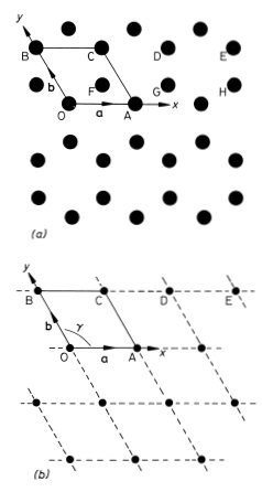
There are many ways of doing this but the conventional choice for graphite is to take OA and OB for the x and y axes as shown in Fig. 1.1(b). Note that the coordinate axes for graphite are not orthogonal. An example of an unconventional choice of coordinate axes for graphite would be to take OA for the x axis as before but to take the OD direction for the y axis. The distances and directions of the nearest lattice points along the x and y axes are specified by the lattice vectors a and b respectively (Fig. 1.1.(b)). The crystal lattice is completely defined by giving the lengths of a and b and the angle γ between them. For graphite we have a = b = 2.46 Å, γ = 120° (1 Å = 1 ångstrom = 10−10 m). The conventional choice of axes for graphite therefore clearly reflects the hexagonal symmetry of the structure; this is not the case for the unconventional choice discussed above.
The positions of all the lattice points of the two-dimensional graphite crystal are reached by drawing all possible vectors of the form
(1.1) 
from the origin, where u and υ take on all possible integer values, positive, negative and zero. That the crystal appears identical when viewed from all the positions given by this equation is an indication that it possesses the important property of translational invariance.
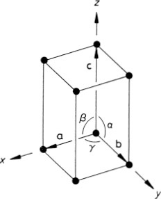
The generalization of the above ideas to a three-dimensional crystal is straightforward. An origin is chosen and all the points within the crystal that are identical to it are identified; this set of points constitutes the three-dimensional crystal lattice. The directions of the crystal coordinate axes are then defined by joining the lattice point at the origin to three of its near neighbours (Fig. 1.2). The choice of neighbours is sometimes obvious but, where this is not the case, convention usually dictates the choice that most clearly reflects the symmetry of the lattice. The distances and directions of the nearest lattice points along the crystallographic x, y and z axes are specified by the three lattice vectors a, b and c. The lattice is completely specified by giving the lengths of a, b and c, and the angles α, β, and γ between them (Fig. 1.2). The positions of all the lattice points are reached by drawing all possible vectors of the form
Fig. 1.2 Crystallographic axes and unit cell for a three-dimensional crystal lattice
(1.2) 
from the origin. The ability to express the positions of the points in this way, with a suitable choice of a, b and c, may be taken as a definition of a lattice in crystallography. A crystalline material may be defined as a material that possesses a lattice of this kind; the translational invariance property of the crystal is that it appears identical from all positions of the form of Eq. (1.2). Note that the only effect of a shift in choice of origin on a crystal lattice is a shift in the lattice as a whole by the same amount.
The lattice vectors also define the unit cell of a crystal. This concept is most easily explained by returning to the two-dimensional graphite crystal of Fig. 1.1, for which the unit cell is the parallelogram OACB defined by the vectors a and b. It is so called because stacking such cells together generates the entire crystal lattice, as is indicated by the broken lines in Fig. 1.1(b). The analogous three-dimensional object in Fig. 1.2, defined by lattice vectors a, b and c, is called a parallelopiped and is the unit cell for the three-dimensional lattice. The unit cell obtained from the conventional choice of lattice vectors is known as the conventional unit cell.
The concept of the unit cell as a building block allows us to understand the remarkable similarities between different crystals of the same material. In particular we can explain the law of constancy of angle (first stated by Nicolaus Steno in 1761) that: In all crystals of the same substance the angles between corresponding faces have a constant value. Fig. 1.3 is an illustration from an early book on mineralogy showing how macroscopically plane faces in various orientations can be built up by using cubic unit cells as building blocks. We shall see in Chapter 12 that the surfaces of crystals are not in fact constructed in the manner suggested by this illustration.
The reader will have noticed that the two-dimensional lattice of graphite (Fig. 1.1(b)) possesses symmetry properties other than the translational invariance indicated by Eq. (1.1). The lattice is transformed into itself, for example, by a rotation of 60° about an axis perpendicular to the xy plane through a lattice point; this axis is the crystallographic z axis of graphite, which is therefore a sixfold rotation axis of the lattice. In 1845 Bravais deduced that any three-dimensional lattice of the form of Eq. (1.2) could be classified into one of 14 possible types according to the symmetry that it possessed. The 14 Bravais lattices contain only one-, two-, three-, four- and six-fold rotation axes.
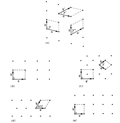
We will not describe all 14 Bravais lattices since only a few will feature in this book, but to illustrate the principle of the classification of lattices by symmetry we consider the corresponding two-dimensional problem. A two-dimensional lattice is specified by a, b and the angle γ between a and b. A lattice with translational symmetry only is shown in Fig. 1.4(a) with three possible choices of primitive unit cell. Lattices of higher symmetry are shown in Figs. 1.4(b)-(e). The rectangular lattice in Fig. 1.4(b) has γ = 90°. Alternatively with a general value of γ we may have a = b, giving the rhombic lattice shown in Fig. 1.4(c). This latter example is interesting in that it shares some symmetries with the rectangular lattice and it can also be described by the rectangular unit cell defined by a′ and b′. This rectangular unit cell has a lattice point at the centre as well as at the corners and the rhombic lattice may therefore also be referred to as a centred rectangular lattice. The unit cell defined by a′ and b′ has an area twice that defined by a and b. The latter is the smallest possible unit cell of the lattice and is said therefore to be a primitive unit cell; the former unit cell is consequently a non-primitive unit cell. We will encounter examples of both primitive and non-primitive three-dimensional unit cells in Section 1.3. To complete our survey of two-dimensional lattices we must consider the possibility a = b combined with a special value of γ. Two cases arise: γ = 60° (or 120°) gives the triangular lattice of Fig. 1.4(d) with each lattice point surrounded by six neighbours at the corners of a regular hexagon; and γ = 90° gives the square lattice of Fig. 1.4(e). The two-dimensional graphite lattice of Fig. 1.1(b) is a triangular lattice.
Fig. 1.3 The way in which the stacking of cubic unit cells can produce crystal faces of different orientations (Hauy, Traite de crystallographie)
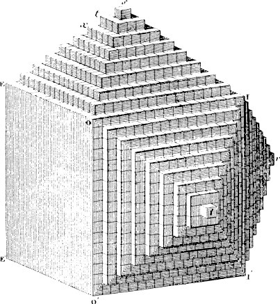
Fig. 1.4 The five possible types of crystal lattice in two dimensions, (a) Lattice with translational symmetry only, showing three possible primitive unit cells, (b) Rectangular lattice, γ = 90°. (c) Rhombic lattice, a = b, equivalent to a centred rectangular lattice with the non-primitive unit cell defined by a′ and b′. (d) Triangular lattice, a = b, γ = 60°. (e) Square lattice, a = b, γ = 90°
Once the crystal lattice has been determined in the way described in the previous section and used to identify suitable coordinate axes and a unit cell, the description of the crystal structure is completed by specifying the contents of the unit cell. This is accomplished by identifying the group of atoms which, when associated with each lattice point, completely generates the structure. This group of atoms is known as the basis of the structure. The basis is specified by giving the position and chemical type of all the atoms within it. We again use the two-dimensional graphite structure of Fig. 1.1(a) to illustrate this procedure. The unit cell OACB of this structure contains the atom F, and readers should convince themselves that a suitable (but not unique) choice of basis for the two-dimensional graphite crystal can be obtained by associating the carbon atoms at O and F with the lattice point at O. This is so because the association of the corresponding pair of atoms with each lattice point (atoms G and A with the lattice point at A, for example) does indeed generate the entire structure. The position of an atom within the cell is most easily described by using the basis vector r, which connects the atom to the origin. Thus the position of the atom at F may be written

This atom is said to be at position ( ,
, ). Our choice of basis for the two-dimensional graphite crystal can therefore be written concisely as

where the chemical type of the atom (carbon in this case) is specified by giving its chemical symbol. That a basis of two atoms is required to specify completely the two-dimensional graphite structure is an indication that each primitive unit cell contains just two atoms. In a three-dimensional crystal the basis vector of an atom can always be written as

and this atom is therefore said to be at (x, y, z).
Taking the symmetry of the basis as well as that of the lattice into consideration allows any crystal to be sorted into one of 32 possible point symmetry groups (sometimes referred to as the 32 crystal classes) and one of 230 possible space symmetry groups. A knowledge of these classifications is not assumed in this book, and readers requiring an understanding of them are recommended to consult one of the standard texts on crystallography.
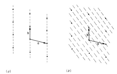
Within a crystal lattice it is possible to identify sets of equally spaced parallel planes. Two examples of sets of lattice planes for a two-dimensional lattice are illustrated in Fig. 1.5. The density of lattice points on each plane of a set is the same and all the lattice points are contained on each set of planes. Planes of lattice points play an important role in the physics of the diffraction of waves by crystals, and it is necessary therefore to have a method of identifying the different sets. Miller indices are used for this purpose. These are derived from the intercepts made on the crystal axes by the plane that is nearest to the origin (but not the one that actually passes through the origin). Thus in Fig. 1.5(b) the nearest plane to the origin has intercepts a/3 and b/2, and this set of planes is therefore referred to by the Miller indices (3 2); note that it is the reciprocal of the intercept that determines the Miller index so that a large index indicates a small intercept. Fig. 1.5(a) illustrates a special case in which one intercept is infinite so that the corresponding Miller index is zero; thus the planes (1 0) are parallel to the y axis.
Fig. 1.5 (a) The (1 0) set of planes in a two-dimensional lattice, (b) The (3 2) set of planes in a two-dimensional lattice
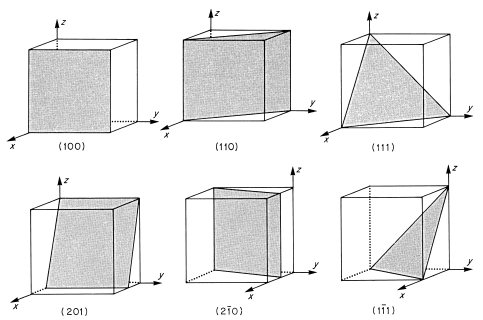
For a set of lattice planes in a three-dimensional lattice the plane nearest the origin will have intercepts a/h, b/k and c/l and the set is referred to by Miller indices (h k l). Some three-dimensional examples are illustrated in Fig. 1.6. The planes (1 0 0) are parallel to both the y and z axes, and hence to the yz plane. Negative intercepts are indicated by a bar over the corresponding index, as in (1  1) and (2
  0). The (

 ) set of planes is however identical to the (h k l) set. Note that if a, b and c define a primitive unit cell, then the Miller indices do not have a common factor. To see why this is, consider the special case of a set of planes with Miller indices (6 4) on Fig. 1.5(b); such a set would be parallel to the (3 2) planes shown but would have half the spacing. The (6 4) planes would therefore have lattice points only on alternate planes.
For crystals of high symmetry certain sets of planes may be related by symmetry and thus be equivalent from an atomic point of view. Thus for crystals of cubic symmetry, in which the unit cell sides a, b and c are equal in magnitude and mutually perpendicular, the three sets of planes (1 0 0), (0 1 0) and (0 0 1) are related by symmetry; they are said to belong to the form {1 0 0} where the curly brackets mean all planes equivalent by symmetry to the given plane.
Fig. 1.6 Some crystal planes inscribed in a unit cell, with their Miller indices
It is often necessary to specify the direction of a vector r in a crystal. The vector can always be written as r = ua + υb + wc and hence the direction is referred to as ‘the [u υ w] direction’ using square brackets. If the direction corresponds to that between two lattice points, as is usually the case, then it follows from Eq. (1.2) that u, υ and w take integer values. It is important to remember that indices in square brackets are not Miller indices, although for cubic crystals it is a consequence of the symmetry that the direction [u υ w] is normal to the planes of Miller indices (u υ w) (problem 1.3). In this case therefore, which we shall mainly use for practical examples, the direction (u υ w) and the planes (u υ w) are simply related.
The crystal structure adopted by a particular material depends on the nature of the forces between the atoms within it. In some solids, particularly the inertgas solids and many metals, the forces are such that, to a good approximation, the atoms look like attracting hard spheres. For minimum energy in such cases it is necessary that the spheres should be packed as closely as possible. In two dimensions this principle leads to the close-packed layer structure shown in Fig. 1.7; this is a two-dimensional crystal in which the centres of the spheres lie on a triangular lattice like that of Fig. 1.4(d). The close packing can be extended to three dimensions if a second close-packed layer is placed over the first such that the spheres in the second layer are centred over interstices in the first. Let us suppose, for example, that the second layer occupies the positions marked B in Fig. 1.7. In this way each sphere in the second layer will touch three spheres in the first and the packing will be as close as possible. Inspection of Fig. 1.7 shows that such packing may be continued in various ways, for a third layer can occupy either positions C or A; both of these sets of positions mark interstices in the second layer.
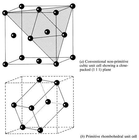
A very common stacking sequence is ABCABC. . ., which gives a structure known as cubic close-packed (ccp) or face-centred cubic (fcc). The cubic unit cell of this structure is shown in Fig. 1.8; there are atoms at the corners of the cell and at the centres of each face. To make clear the relation to Fig. 1.7 a close-packed layer of atoms is shaded in Fig. 1.8; it is a (1 1 1) plane, normal to a body diagonal of the cube. It follows from symmetry that all planes of the form {1 1 1} are close-packed planes. In the fcc structure the environment of every atom is identical so that the crystal lattice corresponds to the atomic structure in this case. The rhombohedral primitive unit cell of the lattice is shown in Fig. 1.8(b). The conventional non-primitive choice of unit cell is however the cubic unit cell of Fig. 1.8(a) because it more obviously shows the full cubic symmetry. The conventional cell has a volume four times that of the primitive cell and thus contains four lattice points. Not surprisingly the lattice of the fcc structure is denoted an fcc lattice in the Bravais classification. Examples of elements that crystallize into the fcc structure are aluminium, calcium, nickel, copper, silver, gold, lead, neon, argon, krypton and xenon.
Fig. 1.7 A close-packed layer of spheres occupying positions A. The adjacent layers can occupy positions B or C
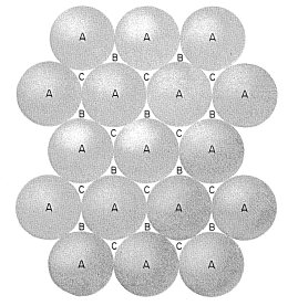
Fig. 1.8 The cubic close-packed (ccp) or face-centred cubic (fcc) structure
The environment of an atom in the fcc structure is best visualized by looking at the atomic coordination polyhedron. This is the figure formed from planes which are the perpendicular bisectors of lines joining an atom to its neighbours. Suppose you built a model of the structure out of Plasticine spheres and then compressed it; if you then picked it apart you would find that the spheres had deformed into coordination polyhedra.†
Fig. 1.9 Coordination polyhedron of the ccp structure: the rhombic dodecahedron. The origin of the crystallographic axes has been shifted so that there is an atom at the centre of the unit cell. The bonds from this atom to its nearest neighbours are shown
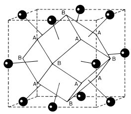
The coordination polyhedron thus represents the ‘sphere of influence’ of an atom. The coordination polyhedron of the fcc structure is shown in Fig. 1.9, together with the positions of the nearest neighbour atoms. Fig. 1.9 shows a cubic unit cell with the origin shifted from that of Fig. 1.8 by half a cell side along a cube axis, the [1 0 0] direction. This polyhedron is called a rhombic dodecahedron; it has 12 faces corresponding to contact with the 12 nearest neighbours; hence each atom is said to have a coordination number of 12. On this polyhedron the symmetries characteristic of the cubic structure (and of the cube itself) may be identified. The rhombic dodecahedron has four three-fold axes of symmetry through opposite pairs of corners A ([1 1 1] directions); it looks the same after rotation by 120° about any of these axes. There are also three four-fold axes through opposite pairs of corners B ([1 0 0] directions) and six two-fold axes through the centres of opposite faces ([1 1 0] directions).
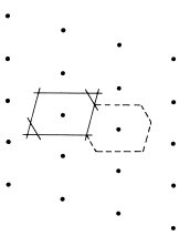
The coordination polyhedra of the fcc structure all stack together in the same orientation in such a way as to fill the whole of space. The polyhedron therefore constitutes an alternative choice of primitive unit cell for the crystal. This type of unit cell is known as a Wigner-Seitz cell after those who first used it for a quantum mechanical problem. A Wigner-Seitz cell is defined for a general lattice as the smallest polyhedron bounded by planes that are the perpendicular bisectors of vectors joining one lattice point to the others; Fig. 1.10 illustrates this method of construction of the Wigner-Seitz cell for a two-dimensional lattice. It follows from the definition that the interior of the cell is the locus of points which are nearer to the given lattice point than any other. Only for the special case that each atom represents a lattice point is the Wigner-Seitz cell also the atomic coordination polyhedron.
Fig. 1.10 The Wigner-Seitz cell (broken lines) of a two-dimensional lattice obtained by drawing the perpendicular bisectors (full lines) of the lines joining a lattice point to its neighbours
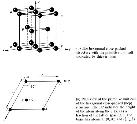
Another common stacking sequence of the close-packed layers in Fig. 1.7 is ABABAB. . . ; this gives the hexagonal close-packed (hcp) structure illustrated in Fig. 1.11(a). All the A-plane atoms in this structure have an identical environment and can therefore be taken as lattice points. The environment of the B-plane atoms is different to that of the A-plane atoms, so that the B-plane atoms do not then lie on lattice points. The resulting lattice is denoted a hexagonal lattice in the Bravais classification. The conventional choice of crystallographic axes for the lattice is shown in Fig. 1.11(a) and the resulting primitive unit cell is identified by the thicker lines. Fig. 1.11(b) is a simpler two-dimensional way of depicting this three-dimensional unit cell. It shows a plan view as seen along the z axis; the z coordinate of the atom in the cell is indicated as a fraction of the side c of the unit cell. The unit cell contains a basis of an A atom at (0, 0, 0) and a B atom at ( ,
, ,
, ). The close-packed A planes in the hcp structure are the (0 0 1) planes, with the B planes sandwiched half-way between.
Since the environments of the A and B atoms are different, their coordination polyhedra have the same shape but differ in orientation. Because there are two atoms in each primitive unit cell, the Wigner-Seitz unit cell of the hcp lattice is double the volume of each coordination polyhedron and does not bear a simple relation to it.
The ratio c/a of the lattice constants for the ‘ideal’ hexagonal close packing of hard spheres can be shown by elementary geometry to equal (8/3)1/2 = 1.633 (problem 1.1). This ideal value is not however imposed by the hexagonal symmetry of the lattice. Since atoms are not really hard spheres, therefore, the unit cell axial ratio c/a differs a little from the ideal value. Examples of elements that crystallize into the hcp structure with the corresponding c/a values in brackets are magnesium (1.623), titanium (1.586), zinc (1.861), cadmium (1.886), cobalt (1.622) and helium (1.633).
Fig. 1.11
Other more complicated stacking sequences of close-packed layers are sometimes found, ABACABAC. . . for example, particularly in the rare-earth metals. These more exotic possibilities will not concern us in this book.
A cubic structure only slightly less close-packed than fcc is the body-centred cubic (bcc) structure, three cubic unit cells of which are shown in Fig. 1.12(a). The environments of all the atoms are identical in the bcc structure so that the lattice is the same as the structure. The non-primitive cubic unit cell is the conventional choice for this lattice and contains two lattice points; the lattice vectors of the primitive cell are shown in Fig. 1.12(a). The eight hexagonal faces of the coordination polyhedron shown in Fig. 1.12(b) represent the ‘contact’ of an atom with its eight nearest neighbours; the coordination number of the bec structure is thus 8. This is smaller than the coordination number (12) of the fcc and hcp structures, but the existence of the six square faces of the coordination polyhedron indicates that an atom in the bcc crystal has six second nearest neighbours not much further away than the first nearest neighbours. The metallic elements lithium, sodium, potassium, chromium, barium and tungsten crystallize into the bcc structure.
Fig. 1.12
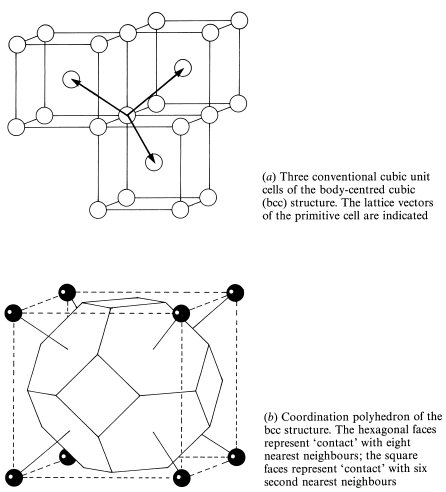
Fig. 1.13 Unit cell of the NaCl structure, with alternate planes of Na+ and Cl− ions perpendicular to the [1 1 1] direction indicated by shading
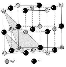
We now progress to consider examples of the simplest type of crystals containing atoms of more then one element, namely ionic solids. Since ions of opposite charge approximate to attracting hard spheres, the crystal structure of these is also often dominated by close-packing considerations. The electrons in the negatively charged anion are in general less tightly bound than those in the positively charged cation and the anion is therefore normally larger. In crystals containing equal numbers of positive and negative ions such as sodium chloride, NaCl, the structure is then likely to be determined by the number of larger anions that will pack tightly around the cation. For NaCl this is only six, and this leads to the three-dimensional chessboard structure shown in Fig. 1.13. All the Na+ ions have identical environments within the crystal so that these can be taken to represent the crystal lattice, which is therefore an example of an fcc Bravais lattice. The Cl− ions also lie on an fcc lattice displaced by half a unit cell in the [1 0 0] direction.
It can also be seen from Fig. 1.13 that planes of the form {1 1 1} of the Na+ lattice contain all the Na+ ions and no Cl− ions; the Cl− ions are contained on parallel planes mid-way between the (1 1 1) planes; this fact was crucial in the elucidation of the structure of NaCl which was the first to be determined by x-ray diffraction (see section 1.4). When this structure was first discovered some chemists were horrified to find that it contained no identifiable NaCl molecule. We now know that the absence of an identifiable molecule is very general in inorganic crystals and we have become used to the idea of a crystal as a single giant molecule.
Fig. 1.14 Primitive cubic unit cell of CsCl shown in plan view. The basis is Cs+ (0,0,0) and Cl− ( ,
,  ,
,  )
)
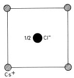
The caesium chloride, CsCl, structure of Fig. 1.14 is an alternative structure for an ionic solid containing equal numbers of anions and cations; the cubic unit cell has Cs+ ions at the corners and a Cl− ion at the centre. Each ion in the structure has a coordination number of 8 so that this is the structure likely to be adopted when just eight anions will pack tightly around each cation. All cations (or alternatively all anions) in this structure have an identical environment so that their positions form a crystal lattice. In this case the conventional cubic unit cell is primitive and is designated as simple cubic in the Bravais classification.
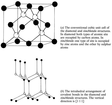
A very important structure in solid state physics is that adopted by carbon atoms in diamond. In this structure each carbon atom is covalently bonded to four nearest neighbours arranged at the corners of a regular tetrahedron as in Fig. 1.15. Fig. 1.15 shows that only half of the atoms have identical environments and these lie on an fcc Bravais lattice. The other atoms form an fcc lattice displaced by one-quarter of a unit cell in the [1 1 1] direction. The two types of atom differ only in the orientation of the bonds to the nearest neighbours. The small coordination number (4) of the diamond structure indicates that it is very far from being a close-packed structure and that the interatomic forces are very different in nature to those in most metallic, ionic and ‘inert-gas’ solids. Two other elements from group IV of the periodic table, the semiconducting elements silicon and germanium, crystallize into the diamond structure and this explains its importance in solid state physics.
Group III–Group V semiconducting compounds (see Chapter 5), such as gallium arsenide, GaAs, and indium antimonide, InSb, crystallize into the closely related zincblende, ZnS, structure. This structure differs from that of diamond only in that one type of carbon atom is replaced by zinc atoms and the other by sulphur atoms.
Fig. 1.15
The wavelength of x-rays is typically 1 Å, comparable to the interatomic spacings in solids. This means that a crystal behaves as a three-dimensional diffraction grating for x-rays. In an optical diffraction experiment it is possible to deduce the spacing of the lines on the grating from the separation of the diffraction maxima; by measuring the relative intensities of different orders information about the structure of the lines on the grating can be obtained. In an exactly similar way, measurement of the separation of the x-ray diffraction maxima from a crystal allows us to determine the size of the unit cell, and from the intensities of the diffracted beams we obtain information on the arrangement of atoms within the cell.
The general laws of diffraction as formulated by von Laue will be considered in Chapter 11. For the present, the simpler and more physical formulation discovered by Bragg and used by him in his earliest structure determinations will suffice. Bragg derived the condition for constructive interference of the x-rays scattered from a set of parallel lattice planes. Consider x-rays incident at a glancing angle θ on one of the planes of the set as shown in Fig. 1.16(a). The figure illustrates that there will be constructive interference of the waves scattered from the two successive lattice points A and B in the plane if the distances AC and DB are equal. This is the case if the scattered wave makes the same angle θ to the plane as the incident wave; the diffracted wave thus looks as though it has been reflected from the plane. The use of the glancing angle θ rather than the angle of incidence is conventional in x-ray crystallography; the reflection condition implies that the x-ray beam is deflected through an angle 2θ. Note that we consider the scattering associated with lattice points rather than atoms because it is the basis of atoms associated with each lattice point that is the true repeat unit of the crystal; the lattice point is the analogue of the line on an optical diffraction grating and the basis represents the structure of the line.
Fig. 1.16(b)