

| Shillingburg/Jacobi/Brackett | Fundamentals of Tooth Preparations |
Fundamentals
of Tooth Preparations
for Cast Metal and Porcelain Restorations
Herbert T. Shillingburg, Jr., D.D.S., F.A.C.D.
David Ross Boyd Professor and Chairman
Richard Jacobi, D.D.S.
Associate Professor
Susan E. Brackett, D.D.S.
Assistant Professor
Department of Fixed Prosthodontics
University of Oklahoma College of Dentistry
Oklahoma City, Oklahoma
Winner, 1988 Book Awards Competition
American Medical Writers Association

Library of Congress Cataloging-in-Publication Data
Shillingburg, Herbert T.
Fundamentals of tooth preparations for cast metal and
porcelain restorations.
Includes bibliographies.
1. Dental cavity preparations. 2. Dental metallurgy.
3. Dental ceramics. 4. Dental ceramic metals.
I. Jacobi, Richard. II. Brackett, Susan E. III. Title.
[DNLM: 1. Dental Cavity Preparation—methods. 2. Dental
Restoration, Permanent—methods. WU 350 S556f]
RK515.S55 1987 617.672 86-18714
ISBN 0-86715-157-9

Second Printing, 1991
© 1987 by Quintessence Publishing Co., Inc.
All rights reserved.
This book or any part thereof must not be reproduced by any means or in any form without the written permission of the publisher.
Lithography: Sun Art Printing Co., Osaka
Composition: The Clarinda Co., Clarinda, IA
Printing and binding: Toppan Printing Co. (HK) Ltd.
Printed in China
Contributors
James C. Kessler, D.D.S.
Associate Professor
Department of Fixed Prosthodontics
University of Oklahoma College of Dentistry
Robert T. Probst, D.D.S., Ph.D.
Associate Professor
Department of Dental Materials
University of Oklahoma College of Dentistry
Frank J. Wiebelt, D.D.S
Associate Professor
Department of Removable Prosthodontics
University of Oklahoma School of Dentistry
Jack E. Willoughby, D.D.S.
Clinical Assistant Professor
Department of Fixed Prosthodontics
University of Oklahoma School of Dentistry
Dedication
This book is dedicated to our parents:
Herbert and Stefi Shillingburg
Herbert and Clara Jacobi
Delbert and Elsie Brackett
We owe them a debt mere words cannot repay.
Contents
Introduction
Chapter 1 Biomechanical Principles of Preparations
Chapter 2 Finish Lines and the Periodontium
Chapter 3 Instrumentation
Chapter 4 Full Veneer Crowns
Chapter 5 Maxillary Posterior Three-Quarter Crowns
Chapter 6 Mandibular Posterior Three-Quarter Crowns
Chapter 7 Anterior Three-Quarter Crowns
Chapter 8 Pin-Modified Three-Quarter Crowns
Chapter 9 Seven-Eighths Crowns
Chapter 10 Proximal Half-Crowns
Chapter 11 Inlays
Chapter 12 MOD Onlays
Chapter 13 Anterior Porcelain-Fused-to-Metal Crowns
Chapter 14 Posterior Porcelain-Fused-to-Metal Crowns
Chapter 15 All-Ceramic Crowns
Chapter 16 Preparation Modifications for Damaged Teeth
Chapter 17 Preparation Modifications for Special Situations
Acknowledgments
To Dr. William E. Brown, Dean of the University of Oklahoma College of Dentistry, the authors express their gratitude for creating an atmosphere in which a project of this nature could be done. We also thank the Regents of the University of Oklahoma for granting a sabbatical leave of absence to Dr. Shillingburg. Without that impetus, it is doubtful this book could have been started.
We all tend to view the world in terms of what “I” have done. It is important to remember that we all learn from others and that we all stand on the work of our predecessors. We acknowledge a special debt to Drs. Rex Ingraham, Henry Tanner, Guy Ho, and the late Harold Eissman, all of the University of Southern California, for their unswerving commitment to excellence. We are also indebted to Dr. Donald E. Smith, who is quoted often in this book. His principles and concepts of preparation design form the foundation for much of which appears in the following pages. Thanks to Drs. Robert Dewhirst, Donald Fisher, and Sumiya Hobo. They have been our colleagues and good friends for many years, freely sharing their knowledge and enthusiasm for our profession.
Finally, we express our appreciation to Mr. William Wade of Brasseler, USA, for his repeated assistance in providing information and materials on rotary instruments. Thanks also to Mr. Robert Vaccaro of Syntex Dental Products and Mr. Lonnie Graybill of Union Broach Company for obtaining the information on diamond grits.
Introduction
Cast metal and porcelain restorations are an important part of restorative dentistry. By virtue of their strength and encircling configurations, cast crowns allow the reconstruction of individual teeth and the replacement of lost teeth in a permanent manner not possible by any other treatment mode. Porcelain restorations can be made so that even an expert can have difficulty distinguishing them from their unrestored neighbors. It is quite possible for cast restorations which have been done well and are cared for by well motivated patients to last 30 or even 40 years.1,2 Unfortunately, we see many that do not.
Successful use of cemented restorations, whether of cast metal, porcelain, or a combination of both, begins with accurate diagnosis and thoughtful treatment planning. Only if the material and preparation design are matched with the patient’s needs can the best treatment be rendered. In this age of “fiscodontics” with emphasis placed on daily production quotas, it is worth remembering that the needs of the patient should take precedence over those of the dentist.
The importance of the tooth preparation is often lost in the shuffle of treatment planning, periodontal management, impression materials and techniques, occlusion, cementation, and esthetics. There is a tendency to regard the preparation phase as mundane, technical, and unimportant. After all, it will be “covered up.” No one will ever see it. One dental curriculum planner went so far as to state that he could train chimpanzees to cut full crown preparations. (Perhaps the same chimpanzees that NASA planned to use in the “manned” space program?)
Tooth preparation is a far more important phase of the treatment than that, although some practitioners never realize this. It must be done with skill and meticulous attention to detail, for everything else that follows—pulpal vitality, periodontal health, a good esthetic result, proper occlusion, protection of remaining tooth structure, and the longevity of the restoration itself—will depend on it. Dr. Lloyd Miller summed it up succinctly when he wrote, “No other clinical procedure in fixed prosthodontics reveals . . . the care, skill, and judgment used by a dentist than the quality of tooth preparation.”3
Preparations have not always been that important. Their significance grew steadily as technology made possible an increasingly accurate fit of cast restorations. With improvement in the technology of fabricating restorations, there was a concomitant increase in the complexity of restoration designs and in the demands placed on retainers by more sophisticated prostheses.
Although Fauchard employed a pivot crown with a dowel projecting into the root canal for retention as early as 1746,4 it was Beers’ gold shell crown with solder-filled, swaged cusps, developed in 1849 and patented in 1873, that permitted restoration of a tooth by encircling it.5 This was modified by Matheson to an open-faced crown in 1883, with true partial veneer crowns coming into being with Benneti’s vertical half-cap crown in 1885.4 This concept was developed further as a recognizable three-quarter crown by Carmichael in 1901.6
The early three-quarter crown was not a casting. It was made by flowing solder over gold foil that had been adapted to the tooth preparation, with wrought wire staples in the preparation grooves. Inlays were made in a similar fashion by flowing solder into a foil matrix adapted to the cavity preparation. The fit of both intracoronal and extracoronal restorations was improved when Taggart adapted the lost wax technique to dentistry in 1907.7
During the same time period that new types of all-metal restorations were evolving, efforts were being made to produce restorations that could restore the patient esthetically as well as functionally. A major step in this direction was the development of the porcelain jacket crown by Land in 1886.8
These technological improvements necessitated modifications of existing preparation forms to take full advantage of the restoration design and material. Many dentists in the past 100 years have contributed to the preparation designs and techniques shown on the following pages. Some of the designs and techniques were once tried and abandoned, only to be resurrected years later as a “new development” when instruments or materials became available to make the old concept work.
We have tried whenever we could to identify all of the people associated with an idea, even if they aren’t traditionally credited with its development. We undoubtedly have failed at times, and we apologize to those dentists whose work to elevate the quality of restorative dentistry we have not recognized.
From the beginning, restorative dental procedures have been limited far more by the technology available than by a lack of ingenuity on the part of dentists. G. V. Black’s concept of extension for prevention was governed in part by the primitive instrumentation available in 1891.9 The instruments of his time were large and easily dulled. It was nearly a half a century later before diamond and tungsten carbide cutting instruments were developed for use in dentistry, and the effectiveness of those instruments was not fully realized until handpiece speeds were dramatically increased.
These technological improvements have not decreased the need for skilled, knowledgeable restorative dentists. On the contrary, they have made knowledge and skill that much more critical. Technology in the hands of a skilled operator makes it possible to do more work of an even higher quality. But in the hands of one who has not mastered the skills of his or her profession, that technology merely enables one to do tremendous damage.
It is our desire to provide the reader with a better understanding of the rationale for tooth preparation designs. We hope that we have shown actual techniques clearly enough to help the neophyte master the hands-on skills to become a good restorative dentist. For the advanced student of dentistry, this book furnishes detailed information on less frequently used designs as well as serving as a review of basic principles.
References
1. Smith, D. E. Fixed bridgework in the various phases of dental practice, J. South. Calif, Dent. Assoc. 9:13, 1942.
2. Stibbs, G. D. Individual intracoronal cast restorations. Oper. Dent. 10:138, 1985.
3. Miller, L. A clinician’s interpretation of tooth preparations and the design of metal substructures for metal-ceramic restorations. pp. 173-206 In J. W. McLean (ed.) Dental Ceramics: Proceedings of the 1st International Symposium on Ceramics. Chicago: Quintessence Publishing Co., 1983.
4. Lovel, R. W. The restoration of teeth by crowning. Dent. Pract. 1:336, 1951.
5. Talbot, E. S. Gold crowns. Dent. Cosmos 22:463, 1880.
6. Carmichael, J. P. Attachment for inlay and bridgework. Dent. Rev. 15:82, 1901.
7. Taggart, W. H. A new and accurate method of making gold inlays. Dent Cosmos 49:1117, 1907.
8. Land, C. H. A new system of restoring badly decayed teeth by means of an enamelled coating. Independent Pract. 7:407, 1886.
9. Sigurjons, H. Extension for prevention: Historical development and current status of G. V. Black’s concept. Oper. Dent. 8:57, 1983.
Chapter 1
Biomechanical Principles of Preparations
The design and preparation of a tooth for a cast metal or porcelain restoration are governed by five principles:
1. Preservation of tooth structure
2. Retention and resistance form
3. Structural durability of the restoration
4. Marginal integrity
5. Preservation of the periodontium
At times it may be necessary to compromise one or more for the sake of another. For example, sound tooth structure may have to be sacrificed in order to produce a more retentive form, to create space for the bulk of restorative material necessary for structural durability or an esthetic veneer, and to allow the restoration to seat with close-fitting margins. Sound judgment must be exercised in making these compromises, with the requirements of the individual situation taken into careful consideration.
Preservation of tooth structure
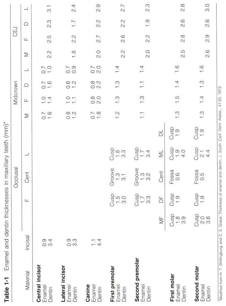
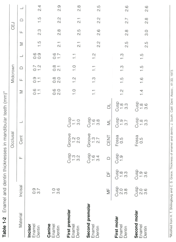
Excessive removal of tooth structure can have many ill effects. If a tooth is overtapered or shortened too much, there will be an unnecessary sacrifice of retention and resistance. Thermal hypersensitivity, pulpal inflammation, and necrosis can result from approaching the pulp too closely. As a guide to how much tooth structure can be safely removed, or how deeply a preparation may extend, the average thicknesses of enamel and dentin for permanent maxillary teeth are given in Table 1-1. Those for mandibular teeth are shown in Table 1-2.
One of the most common violations of this principle is seen in the indiscriminate use of full-coverage porcelain veneered crowns in situations where partial veneer coverage with an all-metal restoration could be used. It is true that full-coverage restorations have long been recognized by clinicians as offering superior retention and resistance.1 This has been borne out in recent years by several studies.2-4 However, the shift in emphasis from partial veneer to full veneer restorations is more probably related to the ease and convenience associated with the design.5-7 The decision to use full coverage should be reached only after a partial veneer crown has been considered and found wanting because of inadequate retention or esthetics.8-11
Preservation of tooth structure entails more than simply avoiding excessive destruction. It also requires designing the restoration so that it will reinforce and protect the remaining enamel and dentin even when this means sacrificing a small amount of additional tooth structure on the occlusal surface to protect underlying cusps.
Retention and resistance
If it does not remain firmly attached to the tooth, a restoration cannot meet its functional, biological, and esthetic requirements. Its capability for retention and resistance must be great enough to withstand the dislodging forces it will encounter in function. Some estimate of the prevailing occlusal forces in an individual patient can be made by noting the degree of wear on the other teeth, the firmness of the opposing teeth, the thickness of the supporting bone, and the bulk of the masticatory muscles. Contrary to the expectations of students, a retainer for a prosthesis requires greater, not less, retention and resistance than does a single tooth restoration.
The geometric form of the preparation is perhaps the most important of the factors under the operator’s control which determine whether or not a restoration will remain cemented to its preparation. It is the geometric form that determines the orientation of the tooth-restoration interfaces to the direction of forces encountered. This in turn determines whether the cement in a given area will be subjected to tension, shear, or compression.
All cements exhibit their greatest strength under compression. They are weakest under tension, with the value for shear strength lying in between. Zinc phosphate cement, for example, has compressive, shear, and tensile strengths, which have been measured at 14,000 psi, 7,900 psi, and 1,300 psi, respectively.12 Where a part of the restoration is pulled directly from the tooth, separation is prevented only by the relatively weak tensile strength and adhesive properties of the cement (Fig. 1-1, A)
Dental cements hold mainly through the mechanical interlocking of projections of cement into small irregularities of the surfaces being joined. Zinc phosphate cement exhibits no specific adhesion, so even its modest tensile strength is not fully utilized before it separates from one of the bonded surfaces. Polycarboxylate and glass ionomer cements claim some true adhesion under proper conditions, but their tensile strengths are still very weak when compared with their respective compressive strengths. The newer technique of bonding etched metal to etched enamel with resins can achieve tensile bonds of 2,270 psi13 to 2,500 psi14 under optimum conditions, but these values are still too low to permit us to ignore geometric retention and resistance form.
If the applied force is parallel with the cement film (Fig. 1-1, B), movement at the cement-tooth and cement-metal interfaces is more effectively impeded by the minute projections of cement into the surface irregularities than when the force is tensile in nature. Movement within the cement film itself is resisted by its relatively greater shear strength. A force directed at an angle toward the restoration has one component parallel with and one component perpendicular to the joined surfaces (Fig. 1-1, C). Thus the cement is subjected to a combination of shear and compression, and movement is resisted more effectively than if the forces were purely tensile or shear in nature. A compressive force perpendicular to the cement film can produce no movement of the restoration relative to the tooth unless it is great enough to crush the cement or deform the structures (Fig. 1-1, D). Such forces are seldom encountered in function.
Retention and resistance can be maximized by shaping the preparation so that as much of its surface as possible will experience compression and shear when the restoration is subjected to an unseating force.
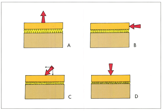
Fig. 1-1 The direction of the force acting upon a segment of a restoration determines the type of stress to which the cement film is subjected. A resultant force directed away from the tooth produces tensile stress (A), while a force parallel with the interface produces shear (B). A force directed at an angle toward the tooth will produce a combination of shear and compression (C). When the force is perpendicular to the tooth, compression results (D).
In practice, retention and resistance are closely related, and they are not always clearly distinguishable. Retention is the ability of the preparation to impede removal of the restoration along its path of insertion. Under this condition, the cement bond is subjected to tension and shear. Resistance, on the other hand, is the ability of the preparation to prevent dislodgment of the restoration by forces directed in an apical, oblique, or horizontal direction. Where there is effective resistance, much of the cement film will be placed under compression, although some parts will still be subjected to tension and shear.
Retention
A restoration can experience withdrawing forces along its path of insertion during mastication of sticky foods. If the restoration is a retainer for a bridge, an apically directed force elsewhere on the prosthesis can produce occlusally directed tensile force on the retainer through leverage. There are four factors under the control of the operator during tooth preparation which influence retention: (1) degree of taper,15 (2) total surface area of the cement film,16 (3) area of cement under shear, and (4) roughness of the tooth surface.17
Taper and retention
The ability of a cement bond to withstand a force depends largely on the direction of the force in relation to the cemented surfaces. From this we would expect that the more nearly parallel the opposing walls of a preparation, the greater will be the retention. This has been verified experimentally by Jorgensen,15 who found that retention decreases as taper increases (Fig. 1-2). Theoretically, the most retentive preparation would be one with parallel walls. However, in order to avoid undercuts and to allow complete seating of the restoration during cementation, the walls must have some taper. One which lies within the range of 2 to 6.5 degrees has been considered to be optimal.18-23 This is based on an inclination of approximately 3 degrees being produced on each surface, external or internal, by the sides of a tapered instrument. The result would be an overall taper or angle of convergence of 6 degrees (Fig. 1-3).
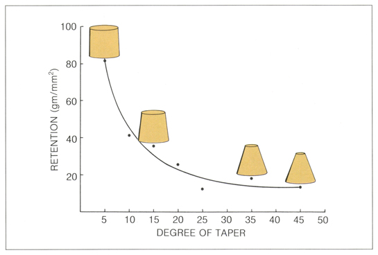
Fig. 1-2 As the degree of taper of a preparation increases, its ability to retain a restoration decreases (after Jørgensen15).
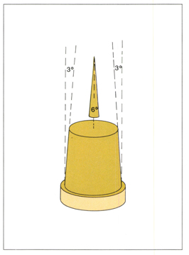
Fig. 1-3 To produce an optimal 6-degree taper, or convergence angle, each opposing axial wall should have an inclination of 3 degrees to the path of insertion.
Studies of actual crown preparations made by students have shown average tapers between 13 and 29 degrees.24-26 Dies taken at random from commercial laboratories by Eames et al. were found to have an average overall taper of 20 degrees.27 Kent and associates found the tapers of preparations done by an experienced operator to average from 8.6 to 26.6 degrees, depending upon location in the mouth and visual accessibility. Grooves and boxes were observed to be markedly less tapered. The overall mean in that study was reported as 14.7 degrees.28
A taper or total convergence of 16 degrees has been proposed as being clinically achievable, while also affording adequate retention.29,30 The tendency for operators to overtaper preparations needlessly must be guarded against in order to produce preparations with minimum taper and maximum retention for any given situation.
Surface area
Obviously, the greater the area of the cement film bound to the preparation and to the internal detail of the casting, the greater the retention of the casting will be. Therefore, the greater the surface area of the preparation, the greater the retention of its restoration.16,31-33 The total surface area of the preparation is influenced by the size of the tooth, the extent of coverage by the restoration, and features such as grooves and boxes that are placed in the preparation.
Area under shear
More important for retention than the total surface area is the area of cement that will experience shearing rather than tensile stress when the restoration is subjected to forces along the path of insertion. To decrease the failure potential, it is essential to minimize tensile stress.34 For the shear strength of the cement to be utilized, the preparation must have opposing walls, i.e., two surfaces of the preparation in separate planes must be nearly parallel with each other and the line of draw. The opposing surfaces may be internal, as the facial and lingual walls of the proximal box of an inlay preparation (Fig. 1-4), or external, such as the axial walls of a full veneer crown preparation (Fig. 1-5). There may also be a combination of internal and external walls in opposition. With the walls in this configuration, the restoration cannot be removed in any direction without overcoming the shear strength of the cement contacting the opposing walls.
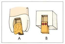
Fig. 1-4 An inlay (A) depends on internal retention to hold it within its preparation. Internal retention is created by the close adaptation of a restoration to two or more opposing, slightly divergent internal walls (arrows, B).
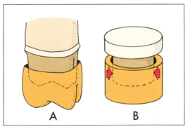
Fig. 1-5 A crown (A) depends primarily on external retention to resist removal. External retention is provided by approximation of the restoration to the opposing external axial walls of the preparation (arrows, B).
To obtain the greatest area of cement under shear, the directions in which a restoration can be removed must be limited to essentially one path.35 As much of the preparation surface as possible must be made nearly parallel with that line of draw. A severely overtapered preparation has many paths along which a tensile force could remove a crown (Fig. 1-6, A); a restoration on such a preparation would encounter many such forces during function. If features are added to the preparation so that only a force in one direction can move a restoration without compressing the cement film against one or more surfaces, retention is enhanced (Fig. 1-6, B). Even against a force along the line of draw, such features enhance retention, not only because they increase the total surface area of the cement film, but because most of the added area is subjected to pure shear with no component of tension.
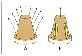
Fig. 1-6 Retention is enhanced by restricting the possible paths of withdrawal or paths of insertion. The excessively tapered truncated cone has an infinite number of paths along which a crown could be withdrawn (A). The addition of parallel-sided grooves (B) limits the path of withdrawal to one direction, thereby reducing the possibility of dislodgment.
A full veneer crown preparation has excellent retention because the mesial, distal, lingual, and facial walls limit the possible paths of insertion to a narrow range (Fig. 1-7, A). However, if the facial surface is left unveneered, the crown placed on this preparation could be removed toward the lingual, the incisal, or any direction in between (Fig. 1-7, B). To create a more retentive form, grooves, boxes, or pinholes are substituted for the missing axial wall (Fig. 1-8).36 These features are also useful for augmenting retention on severely damaged teeth.
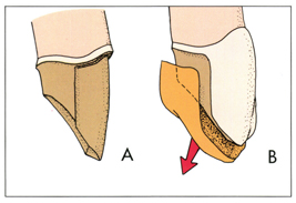
Fig. 1-7 A preparation for a porcelain-fused-to-metal crown has a limited path of insertion and excellent retention (A). However, if one of the four axial walls is missing or left uncovered (B), the potential paths of withdrawal are greatly increased and retention is compromised.
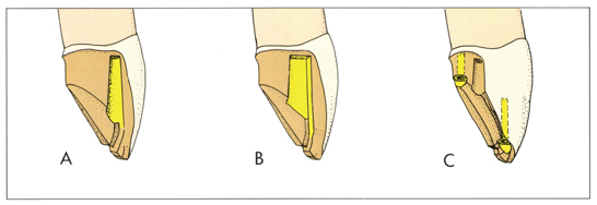
Fig. 1-8 When an axial wall is left unveneered, retention is achieved by substituting grooves (A), boxes (B), or pinholes (C) for the missing wall.
In order for a groove to effectively substitute for the uncovered facial wall, the lingual wall of the groove must be distinct and perpendicular to the adjoining axial surface (Fig. 1-9, A). Otherwise a lingually directed displacing force could cause the ribs of metal in the crown to slide along the inclined planes of the lingual walls of grooves, spreading the axial walls and opening the margins (Fig. 1-9, B)
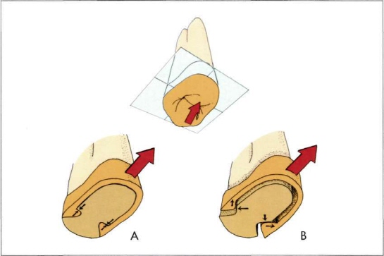
Fig. 1-9 A lingually directed force acting on a three-quarter crown is effectively resisted if the lingual walls of the groove are perpendicular to the path of displacement (A). However, the walls of V-shaped grooves will act as inclined planes which will eventually cause the walls of the restoration to spread (B).
The length of the preparation is an important factor in retention: a long preparation has greater retention than does a short preparation.31,32,37 This is due, at least in part, to its greater surface area (Fig. 1-10), and to the fact that most of the additional area is under shear rather than tension.
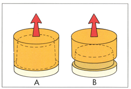
Fig. 1-10 All other factors remaining constant, the greater the surface area of cement film, the greater the retention. Therefore, a restoration on a long preparation (A) can withstand a force that could remove a restoration from a shorter preparation of equal diameter (B). Doubling the height of a preparation would nearly double the area of its axial walls.
Because of its greater surface area, a preparation with a larger diameter (and circumference) will have greater retention than will a narrow preparation of the same length (Fig. 1-11).31,38
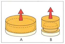
Fig. 1-11 Of two preparations of equal height and taper, the wider (A) will have greater retention than the narrower (B). Doubling the diameter of a preparation doubles the area of its axial walls under shear, and quadruples the area of the occlusal surface, where the cement is under tension.
Surface roughness
Because the adhesion of dental cements depends primarily on projections of the cement into microscopic irregularities and recesses on the surfaces being joined, the prepared tooth surface should not be highly polished. Øilo and Jorgensen found retention of castings cemented with zinc phosphate cement on test dies with a 10-degree taper to be twice as great on preparations with 40 μm scratches as on those with 10 μm scratches,17 while Smith found no significant difference in castings cemented on 14-degree taper preparations whose roughness varied by a factor of 24 from smoothest to roughest.39
Resistance
Resistance prevents dislodgment of a restoration by forces directed in an apical, oblique, or horizontal direction. If the cement film is disrupted by the restoration’s sliding or tipping on its preparation the smallest fraction of a millimeter, the restoration is doomed through percolation of fluids, dissolution of the cement, and recurrent caries. Resistance to sliding and tipping must be designed into a preparation by forming walls to block the anticipated movements. The more nearly perpendicular it lies to the force, the greater is the resistance provided by the supporting surface, because the cement will be compressed,40 and failures are less likely to occur from compression than shear.41
Leverage and resistance
The strongest forces encountered in function are apically directed and can produce tension and shear in the cement film only through leverage. Leverage, probably the predominant factor in the dislodgment of cemented restorations, occurs when the line of action of a force passes outside the supporting tooth structure, or when the structures flex. For the sake of simplicity, all structures in the following situations will be considered to be rigid.
If the force passes within the margin of a crown, there will be no tipping of the restoration (Fig. 1-12, A). The margin on all sides of the restoration is supported by the preparation. The torque produced merely tends to seat the crown further. If the occlusal table of the restoration is wide, even a vertical force can pass outside the supported margin and produce destructive torque (Fig. 1-12, B). This can also occur in crowns on tipped teeth and retainers for cantilever bridges.
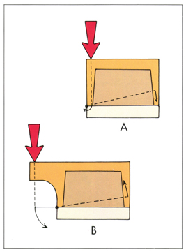
Fig. 1-12 When the line of action of an applied force passes within the margins of the restoration, no secondary lifting forces are produced (A). When the line of action passes outside the margins of the restoration, a torque is produced that will tend to tip or rotate the crown around a point on the margin (B).
A force applied to a cemented crown at an oblique angle can also produce a line of action which will pass outside the supporting tooth structure (Fig. 1-13). The point on the margin that lies closest to the line of action is the fulcrum point, or center of rotation. The magnitude of the torque produced is equal to the applied force multiplied by its lever arm, which is the closest distance between the line of action and the fulcrum. In equilibrium, this torque is balanced by the sum of all the resisting tensile, shear, and compressive stresses generated in the cement film. The farther these resisting forces lie from the fulcrum, the greater their mechanical advantage is.
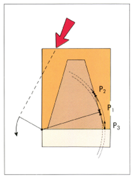
Fig. 1-13 At P1 the arc of rotation is tangent to the surface of the preparation, and the cement film is subject only to shear. There is a component of compression at P2 and at all points occlusal to P1, which becomes greater the higher the point is located. At P3 and all points apical to the tangent point, stresses have a component of tension. Mechanical resistance is provided only by points occlusal to the tangent point.
If a line is drawn from the center of rotation perpendicular to the cement film on the opposite wall of the preparation, the point where this line intercepts the cement film can be referred to as the tangent point. At this point, the arc of rotation around the fulcrum is tangent to the surface of the preparation, and the cement film is subject to shear only. All points occlusal to the tangent point are subject to shear and compression. The compression component becomes greater the farther a point lies above the tangent point. A point near the occlusal end of the preparation would contribute more to resistance than would a site near the tangent point, not only because of the mechanical advantage of its longer lever arm, but also because the force is directed at a steeper angle toward the surface of the preparation.
If a line is drawn connecting the tangent points of all the arcs around the axis of rotation, the cement film along that line would be subjected to pure shear by any force applied perpendicularly to the axis of rotation (Fig. 1-14). The area encompassed by this tangent line has been referred to as the “resisting area” by Hegdahl and Silness.42 Within this area, the luting material is subjected to varying degrees of compression as well as shear, while all other points on the surface of the preparation will experience some degree of tension and will contribute little to the resistance of the preparation.
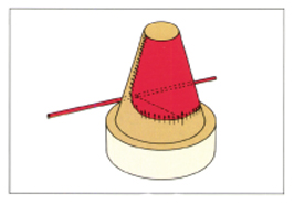
Fig. 1-14 If the tangent points of all the arcs of rotation around a given axis are connected, they form the tangent line. The area above the tangent line (red) is the resisting area, which prevents tipping of a restoration around the axis (after Hegdahl and Silness42). For a preparation to have effective resistance, the tangent line should extend at least halfway down the preparation.
Preparation length and resistance
The length of a preparation has a strong influence on its resistance. Shortening a preparation will produce a proportionally greater diminution of the resisting area (Fig. 1-15). The ability of a restoration to resist tipping depends not only on the preparation, but also on the magnitude of the torque. If two crowns of unequal length on two preparations of equal length are subjected to identical forces, the longer crown is more likely to fail because the force on it acts through a longer lever arm (Figs. 1-16 and 1-17).
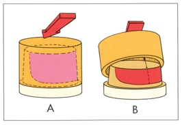
Fig. 1-15 Decreasing the length of a tapered preparation causes a disproportionate decrease in the resisting area. A crown with relatively long axial walls can resist a strong tipping force (A). Although preparation B still has more than half the length of preparation A, it has less than half the resisting area. Its crown will fail under a force that would be easily resisted by the longer preparation (B).
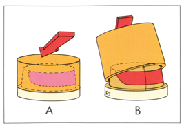
Fig. 1-16 A short restoration on a short preparation is less likely to fail through tipping than is a long restoration on the same preparation. The resistance of this preparation is adequate to prevent the crown from tipping under the applied force (A). Although the preparation and the applied force in (B) are identical to those in (A), the crown fails because of the greater height of the restoration.
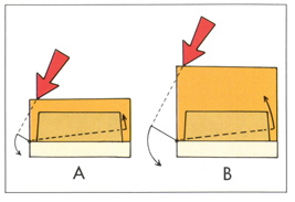
Fig. 1-17 The length of the primary lever arm is the shortest distance from the line of action of the force to the nearest margin. On the short crown the lifting force is small because the primary lever arm is short (A). With a long crown (B), the same force produces a greater torque because its line of action passes farther from the point of rotation.
When a relatively long crown must be made on a short preparation, additional resistance form, usually in the form of a pin-retained core, must be created before the cast restoration can be made. Techniques for this are discussed in greater detail in chapter 16.
Resistance and tooth width
As explained earlier, a wide preparation has greater retention than a narrower one of equal height. Under some circumstances a crown on the narrow tooth can have greater resistance to tipping than one on the wider tooth. This occurs because the crown on the narrower tooth has a shorter radius of rotation resulting in a lower tangent line and a larger resisting area (Fig. 1-18). This advantage is offset, in part, by the shorter lever arm of the narrow tooth and by its diminished axial surface area.
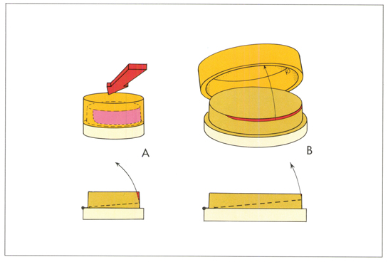
Fig. 1-18 Because of the small diameter, the tangent line of this narrow preparation falls low on the wall opposite the axis of rotation, resulting in a large resisting area (A). Preparation A is wider than preparation B, but its height and taper are the same. Because of the much greater radius of the arc of rotation, its resisting area is smaller than that of the narrower preparation.
The resistance of a preparation on a wide, short tooth can be greatly enhanced by the addition of grooves (Fig. 1-19). The shorter radius of rotation between the fulcrum point and the groove causes the arc of rotation to be tangent to the resisting surface on the groove wall at a lower point than does the longer radius on the more distant axial wall. A large area of the groove wall lies at a relatively steep angle to the arc of rotation, affording increased resistance.
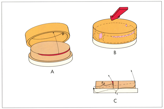
Fig. 1-19 The weak resistance of a short, wide preparation (A) can be enhanced by the addition of vertical grooves (B). From the side (C), it can be seen that the arc of radius r2 is effectively blocked by the resisting area of the groove walls, while the arc of radius r1 encounters little or no resistance on the far axial wall.
Taper and resistance
The resisting area of a cylindrical preparation would include half of its axial surface (Fig. 1-20, A). As the degree of taper increases, the tangent line approaches the occlusal surface, and the resisting area decreases (Fig. 1-20, B and C). The more tapered a preparation, the less its resistance. A short tooth can be easily overtapered to the extent that it has no resistance form at all.
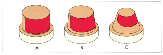
Fig. 1-20 The resisting area decreases as the preparation taper increases. For a cylinder with no taper, the resisting area would cover half the axial walls (A). For an ideally-tapered tooth preparation the resisting area covers somewhat less than half the axial walls (B). An over-tapered (20 degrees) preparation has only a small resisting area near the occlusal surface (C).
A long, narrow preparation can have a greater taper than a short and wide one without jeopardizing resistance. Conversely, the walls of a short, wide preparation must be kept nearly parallel to achieve adequate resistance form. The permissible taper of a preparation is directly proportional to the height/ width ratio. The preparation taper that will still permit an effective resisting area, for a preparation in which the height equals the width, is double that permissible in a preparation in which the height is only one-half of the width (Fig. 1-21). The maximum allowable preparation tapers for various preparation height and width combinations are shown in Table 1-3.
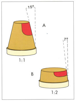
Fig. 1-21 The inclination of the walls of a preparation that will still provide effective resistance is dependent on the height/width ratio. A preparation with a height/width ratio of 1:1 (A) can have a wall inclination of 15 degrees and still have effective resistance. A preparation with a ratio of 1:2 (B) can have an individual wall inclination no greater than 7 degrees without seriously compromising resistance. Resistance is arbitrarily considered effective if the resisting area extends at least halfway down the axial wall.
| Table 1-3 | Preparation dimensions and maximum preparation tapers* | |||||||||||
| Preparation diameter (mm) | ||||||||||||
| Preparation height (mm) |
3 | 4 | 5 | 6 | 7 | 8 | 9 | 10 | 11 | 12 | 13 | 14 |
| degrees | ||||||||||||
| 2 | 16 | 12 | 10 | 8 | 7 | 6 | 6 | 5 | 5 | 4 | 4 | 4 |
| 3 | 24 | 18 | 14 | 12 | 10 | 9 | 8 | 7 | 7 | 6 | 6 | 5 |
| 4 | 33 | 24 | 19 | 16 | 14 | 12 | 11 | 10 | 9 | 8 | 8 | 7 |
| 5 | 33† | 31 | 24 | 20 | 17 | 15 | 13 | 12 | 11 | 10 | 9 | 9 |
| 6 | 28† | 37 | 29 | 24 | 21 | 18 | 16 | 14 | 13 | 12 | 11 | 10 |
| 7 | 24† | 32† | 35 | 28 | 24 | 21 | 19 | 17 | 15 | 14 | 13 | 12 |
| 8 | 21† | 28† | 35† | 33 | 28 | 24 | 21 | 19 | 17 | 16 | 15 | 14 |
| 9 | 19† | 25† | 31† | 37† | 31 | 27 | 24 | 22 | 20 | 18 | 17 | 15 |
| 10 | 17† | 23† | 28† | 33† | 35 | 31 | 27 | 24 | 22 | 20 | 18 | 17 |
| *Calculations are based on an assumption of a symmetrical tooth preparation, with straight axial walls and an area of maximum resistance that is 80% of the preparation height. †This is the maximum possible preparation taper for the given preparation height and diameter. |
||||||||||||
The formulas used in calculating allowable preparation tapers (convergence angles) and for determining the height of the tangency point and preparation height are:
T = arc sin (2r/w),
r = (w sin T)/ 2, and
h = [w tan (90° - T/2)] / 2.
T = preparation taper in degrees
r = height of tangency point in mm
w = preparation width in mm
h = preparation height in mm
Rotation around a vertical axis
Although the previous examples have dealt exclusively with tipping or rotation of the restoration around a horizontal axis, rotation about a vertical axis is also possible. When a crown is subjected to an eccentric horizontal force, moments of torque occur around a vertical as well as a horizontal axis (Fig. 1-22). A three-quarter crown without grooves has little resistance to rotational displacement (Fig. 1-23, A). The addition of grooves places a resisting surface at right angles to the arc of rotation, effectively blocking it (Fig. 1-23, B)
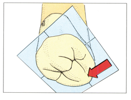
Fig. 1-22 The horizontal component of occlusal force can have a rotating influence on a crown in a horizontal plane.
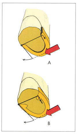
Fig. 1-23 A partial veneer crown which has no grooves (A) has little resistance to rotation around a vertical axis. When grooves are present, their lingual walls provide resistance by blocking the arc of rotation (B).
It is possible for a full crown on a cylindrical preparation to rotate enough to break the cement bond before any compressive resistance is encountered (Fig. 1-24, A). Geometric forms such as grooves or “wings” (Fig. 1-24, B) increase resistance by blocking rotation around a vertical axis.
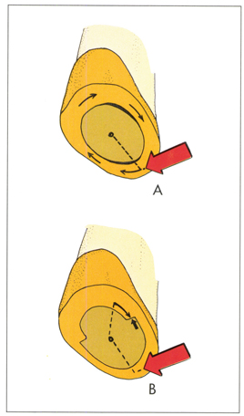
Fig. 1-24 The axial symmetry of a full veneer crown preparation may allow rotation of the restoration around the preparation (A). Resistance can be gained by forming vertical planes (wings) which are perpendicular to the arc of rotation (B).
Path of insertion
Before any tooth structure is cut, the path of insertion should be decided upon, keeping in mind the principles discussed previously. This is especially important when preparing bridge abutments, because multiple paths of insertion must be parallel. A path must be selected that will allow the margins of the retainers to fit against their respective preparation finish lines with the removal of minimum sound tooth structure. This path should not encroach upon the pulp or adjacent teeth.
The path of insertion for posterior full and partial veneer crowns is usually parallel with the long axis of the tooth (Fig. 1-25). However, paralleling the path of insertion of an anterior three-quarter crown with the long axis of the tooth will produce an unesthetic display of metal on the facial surface (Fig. 1-26, A). The remaining incisal tooth structure will also be undermined, making it susceptible to fracture. Instead, the path of insertion for an anterior three-quarter crown should be inclined to parallel the incisal two-thirds of the facial surface (Fig. 1-26, S), enabling the restoration to have almost no metal visible on the facial surface. This inclination also permits longer grooves with better retention and resistance.
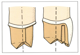
Fig. 1-25 The ideal path of insertion for a posterior full or partial veneer crown is parallel with the long axis of the tooth.
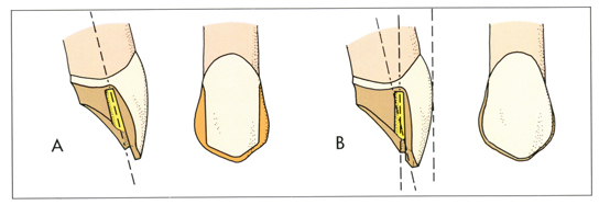
Fig. 1-26 Making the path of insertion of an anterior three-quarter crown parallel with the long axis of the tooth would result in an unnecessary display of metal (A). The preferred path of insertion for an anterior preparation parallels the incisal two-thirds of the labial surface (B). This not only will minimize the display of metal, but allow the grooves to be longer and more retentive.
Normally, for a full crown to have structural durability with proper contours, its path of insertion would parallel the long axis of the tooth (Fig. 1-27, A). However, if the tooth is tilted (Fig. 1-27, B), a path of insertion paralleling the long axis of the tooth may be blocked by the proximal contours of the adjacent tooth (Fig. 1-27, C). In this case, the path of insertion is made perpendicular to the occlusal plane (Fig. 1-27, D).
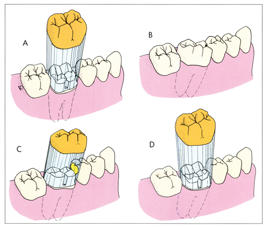
Fig. 1-27 The path of insertion for a full veneer crown on a posterior tooth in normal alignment parallels the long axis of the tooth (A). A tipped tooth must be handled differently (B). If the path of insertion on a tipped tooth parallels the long axis, the crown will be prevented from seating by those parts of the adjacent teeth which protrude into the path of insertion (C). The correct path of insertion for such a tooth is perpendicular to the occlusal plane (D).
Long-standing loss of proximal contact is usually accompanied by tipping of the adjacent tooth into the space (Fig. 1-28, A). When this occurs, a path of insertion parallel with the long axis of the tooth might not allow a crown to seat even if its distal wall were grossly undercontoured (Fig. 1-28, B). The space between the adjacent teeth must be made greater than the mesiodistal diameter of the prepared tooth at the gingival finish line. An acceptable compromise can be reached by inclining the path of insertion so that removal of equal amounts of enamel from each of the adjacent teeth will allow a crown to seat on the prepared tooth (Fig. 1-28 C). If the loss of space is so great that more than 50% of the thickness of enamel would have to be removed from either adjacent tooth, or if there isn’t space for adequate gingival embrasures, the teeth should be separated and uprighted orthodontically.
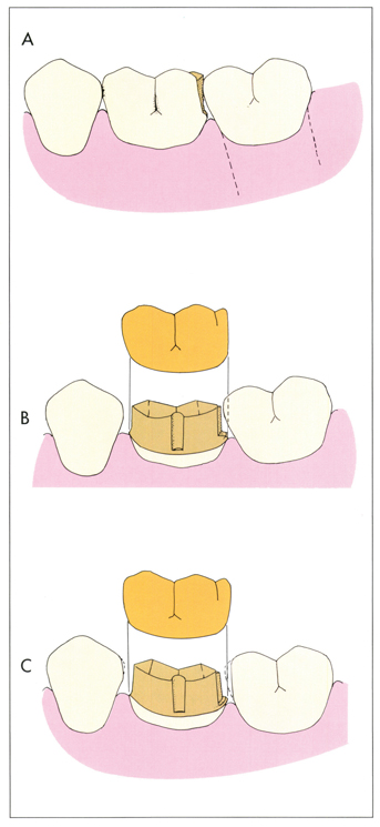
Fig. 1-28 A tooth has migrated into the space formed by a longstanding carious lesion (A). A vertical path of insertion will not permit seating without removal of excessive amounts of tooth structure from the proximal surface of the adjacent tooth (B). The problem can be solved less destructively by inclining the path of insertion slightly to the mesial, and removing small amounts of enamel from both adjacent teeth (C). More severe collapse may require orthodontic uprighting to regain needed space.
All negative taper, or undercut, must be eliminated or it will prevent the restoration from seating. To evaluate preparation taper, view it with one eye from a distance of approximately 30 cm or 12 in. (Fig. 1-29). In this way it is possible to simultaneously see all the axial walls of a preparation with an adequate taper. An undercut as great as 8 degrees can be overlooked if both eyes are used (Fig. 1-30).
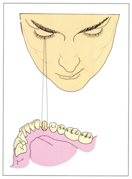
Fig. 1-29 When viewed with one eye from a distance of 30 cm, all the axial surfaces of a preparation with an ideal taper or angle of convergence of 6 degrees can be seen.
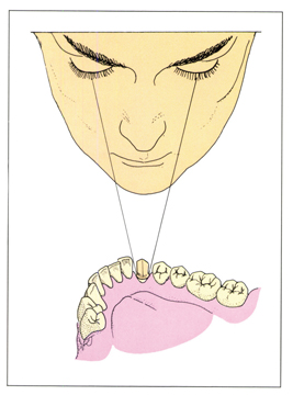
Fig. 1-30 Binocular vision should never be employed to evaluate a preparation for correct taper. With both eyes open, a preparation that is undercut can appear to have an acceptable degree of taper.
Where it is difficult to survey the preparation with direct vision, use a mouth mirror (Fig. 1-31). The entire finish line should be visible to one eye from one fixed position with no obstruction by any part of the prepared tooth or any adjacent tooth. To verify parallel paths of insertion of bridge abutments, the image of one preparation is centered in the mirror. Then, using firm finger rests, the mirror is moved bodily without changing its angulation, until the image of the second preparation is also centered (Fig. 1-32). If the angulation of the mirror must be changed in order to see all of the finish lines, there is a discrepancy between the paths of insertion of the preparations.
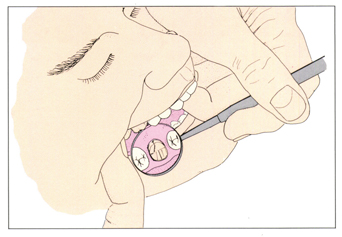
Fig. 1-31 A mirror is used to evaluate a preparation where direct vision is not possible. An unobstructed view of the entire finish line barely outside the circumference of the occlusal surface indicates correct taper.